Previously, we have seen textures used to vary surface parameters. But we can use textures to vary something else: light intensity. In this way, we can simulate light sources who's intensity changes with something more than just distance from the light.
Our first effort in varying light intensity with textures will be to build an incandescent flashlight. The light beam from a flashlight is not a single solid intensity, due to the way the mirrors focus the light. A texture is the simplest way to define this pattern of light intensity.
Before we can look at how to use a texture to make a flashlight, we need to make a short digression. Perspective projection will be an important part of how we make a texture into a flashlight, so we need to revisit perspective projection. Specifically, we need to look at what happens when transforming after a perspective projection operation.
Open up the project called Double Projection. It renders four objects, using various textures, in a scene with a single directional light and a green point light.
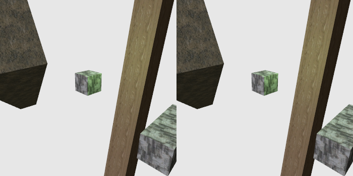
This tutorial displays two images of the same scene. The image on the left is the view of the scene from one camera, while the image on the right is the view of the scene from another camera. The difference between the two cameras is mainly in where the camera transformation matrices are applied.
The left camera works normally. It is controlled by the left mouse button, the mouse wheel, and the WASD keys, as normal. The right camera however provides the view direction that is applied after the perspective projection matrix. The sequence of transforms thus looks like this: Model -> Left Camera -> Projection -> Right Camera. The right camera is controlled by the right mouse button; only orientation controls work on it.
The idea is to be able to look at the shape of objects in normalized device coordinate (NDC) space after a perspective projection. NDC space is a [-1, 1] box centered at the origin; by rotating objects in NDC space, you will be able to see what those objects look like from a different perspective. Pressing the SpaceBar will reset the right camera back to a neutral view.
Note that post-perspective projection space objects are very distorted, particularly in the Z direction. Also, recall one of the fundamental tricks of the perspective projection: it rescales objects based on their Z-distance from the camera. Thus, objects that are farther away are physically smaller in NDC space than closer ones. Thus, rotating NDC space around will produce results that are not intuitively what you might expect and may be very disorienting at first.
For example, if we rotate the right camera to an above view, relative to whatever the left camera is, we see that all of the objects seems to shrink down into a very small width.
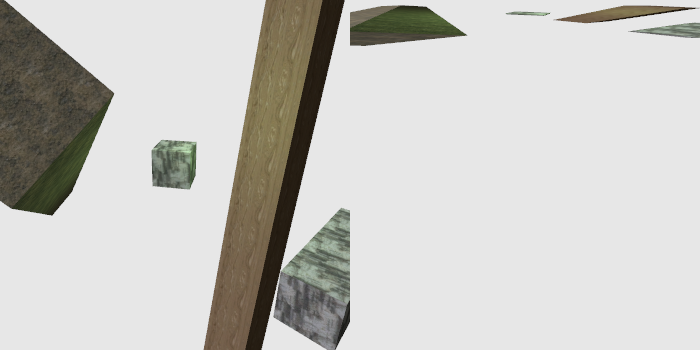
This is due to the particulars of the perspective projection's work on the Z coordinate. The Z coordinate in NDC space is the result of the clip-space Z divided by the negative of the camera-space Z. This forces it into the [-1, 1] range, but the clip-space Z also is affected by the zNear and zFar of the perspective matrix. The wider these are, the more narrowly the Z is compressed. Objects farther from the camera are compressed into smaller ranges of Z; we saw this in our look at the effect of the camera Z-range on precision. Close objects use more of the [-1, 1] range than those farther away.
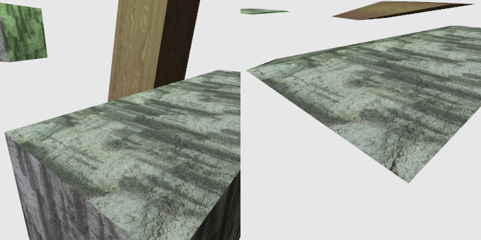
This can be seen by moving the left camera close to an object. The right camera, from a top-down view, has a much thicker view of that object in the Z direction.
Pressing the Y key will toggle depth clamping in the right camera. This can explain some of the unusual things that will be seen there. Sometimes the wrong objects will appear on top of each other; when this happens, it is almost always due to a clamped depth.
The reason why depth clamping matters so much in the right screen is obvious if you think about it. NDC space is a [-1, 1] cube. But that is not the NDC space we actually render to. We are rendering to a rotated portion of this space. So the actual [-1, 1] space that gets clipped or clamped is different from the one we see. We are effectively rotating a cube and cutting off any parts of it that happen to be outside of the cubic viewing area. And since the initial cube is so skewed to far Z values, often times large chunks of the world fall out of the viewing cube.
This is the first code in the tutorial to use the scene graph part of the
framework. The term scene graph refers to a piece of software
that manages a collection of objects, typically in some kind of object hierarchy. In
this case, the Scene.h part of the framework contains a class
that loads an XML description of a scene. This description includes meshes, shaders,
and textures to load. These assets are then associated with named objects within the
scene. So a mesh combined with a shader can be rendered with one or more
textures.
The purpose of this system is to remove a lot of the boilerplate code from the tutorial files. The setup work for the scene graph is far less complicated than the setup work seen in previous tutorials.
As an example, here is the scene graph to load and link a particular shader:
Example 17.1. Scene Graph Shader Definition
<prog
    xml:id="p_unlit"
    vert="Unlit.vert"
    frag="Unlit.frag"
    model-to-camera="modelToCameraMatrix">
    <block name="Projection" binding="0"/>
</prog>
The xml:id gives it a name; this is used by objects in the
scene to refer to this program. It also provides a way for other code to talk to it.
Most of the rest is self-explanatory. model-to-camera deserves
some explanation.
Rendering the scene graph is done by calling the scene graph's render function
with a camera matrix. Since the objects in the scene graph store their own
transformations, the scene graph combines each object's local transform with the
given camera matrix. But it still needs to know how to provide that matrix to the
shader. Thus, model-to-camera specifies the name of the
mat4 uniform that receives the model-to-camera transformation
matrix. There is a similar matrix for normals that is given the inverse-transpose of
the model-to-camera matrix.
The block element is the way we associate a uniform block in
the program with a uniform block binding point. There is a similar element for
sampler that specifies which texture unit that a particular
GLSL sampler is bound to.
Objects in scene graph systems are traditionally called “nodes,” and this scene graph is no exception.
Example 17.2. Scene Graph Node Definition
<node
    name="spinBar"
    mesh="m_longBar"
    prog="p_lit"
    pos="-7 0 8"
    orient="-0.148446 0.554035 0.212003 0.791242"
    scale="4">
    <texture name="t_stone_pillar" unit="0" sampler="anisotropic"/>
</node>
Nodes have a number of properties. They have a name, so that other code can reference them. They have a mesh that they render and a program they use to render that mesh. They have a position, orientation, and scale transform. The orientation is specified as a quaternion, with the W component specified last (this is different from how glm::fquat specifies it. The W there comes first). The order of these transforms is scale, then orientation, then translation.
This node also has a texture bound to it. t_stone_pillar was a
texture that was loaded in a texture command. The
unit property specifies the texture unit to use. And the
sampler property defines which of the predefined samplers to
use. In this case, it uses a sampler with ansiotropic filtering to the maximum
degree allowed by the hardware. The texture wrapping modes of this sampler are to
wrap the S and T coordinates.
This is what the C++ setup code looks like for the entire scene:
Example 17.3. Double Projection LoadAndSetupScene
std::auto_ptr<Framework::Scene> pScene(new Framework::Scene("dp_scene.xml"));

std::vector<Framework::NodeRef> nodes;
nodes.push_back(pScene->FindNode("cube"));
nodes.push_back(pScene->FindNode("rightBar"));
nodes.push_back(pScene->FindNode("leaningBar"));
nodes.push_back(pScene->FindNode("spinBar"));

AssociateUniformWithNodes(nodes, g_lightNumBinder, "numberOfLights");
SetStateBinderWithNodes(nodes, g_lightNumBinder);

GLuint unlit = pScene->FindProgram("p_unlit");
Framework::Mesh *pSphereMesh = pScene->FindMesh("m_sphere");

//No more things that can throw.
g_spinBarOrient = nodes[3].NodeGetOrient();
g_unlitProg = unlit;
g_unlitModelToCameraMatrixUnif = glGetUniformLocation(unlit, "modelToCameraMatrix");
g_unlitObjectColorUnif = glGetUniformLocation(unlit, "objectColor");

std::swap(nodes, g_nodes);
nodes.clear();	//If something was there already, delete it.

std::swap(pSphereMesh, g_pSphereMesh);

Framework::Scene *pOldScene = g_pScene;
g_pScene = pScene.release();
pScene.reset(pOldScene);	//If something was there already, delete it.
This code does some fairly simple things. The scene graph system is good, but we
still need to be able to control uniforms not in blocks manually from external code.
Specifically in this case, the number of lights is a uniform, not a uniform block.
To do this, we need to use a uniform state binder,
g_lightNumBinder, and set it into all of the nodes in the
scene. This binder allows us to set the uniform for all of the objects (regardless
of which program they use).
The p_unlit shader is never actually used in the scene graph;
we just use the scene graph as a convenient way to load the shader. Similarly, the
m_sphere mesh is not used in a scene graph node. We pull
references to both of these out of the graph and use them ourselves where needed. We
extract some uniform locations from the unlit shader, so that we can draw unlit
objects with colors.
Note
The code as written here is designed to be exception safe. Most of the functions that find nodes by name will throw if the name is not found. What this exception safety means is that it is easy to make the scene reloadable. It only replaces the old values in the global variables after executing all of the code that could throw an exception. This way, the entire scene, along with all meshes, textures, and shaders, can be reloaded by pressing Enter. If something goes wrong, the new scene will not be loaded and an error message is displayed.
Two of the objects in the scene rotate. This is easily handled using our list of
objects. In the display method, we access certain nodes and
change their transforms them:
g_nodes[0].NodeSetOrient(glm::rotate(glm::fquat(),
    360.0f * g_timer.GetAlpha(), glm::vec3(0.0f, 1.0f, 0.0f)));

g_nodes[3].NodeSetOrient(g_spinBarOrient * glm::rotate(glm::fquat(),
    360.0f * g_timer.GetAlpha(), glm::vec3(0.0f, 0.0f, 1.0f)));
We simply set the orientation based on a timer. For the second one, we previously stored the object's orientation after loading it, and use that as the reference. This allows us to rotate about its local Z axis.
The split-screen trick used here is actually quite simple to pull off. It's also one of the advantages of the scene graph: the ability to easily re-render the same scene multiple times.
The first thing that must change is that the projection matrix cannot be set in
the old reshape function. That function now only sets the new
width and height of the screen into global variables. This is important because we
will be using two projection matrices.
The projection matrix used for the left scene is set up like this:
Example 17.4. Left Projection Matrix
glm::ivec2 displaySize(g_displayWidth / 2, g_displayHeight);

{
    glutil::MatrixStack persMatrix;
    persMatrix.Perspective(60.0f, (displaySize.x / (float)displaySize.y), g_fzNear, g_fzFar);

    ProjectionBlock projData;
    projData.cameraToClipMatrix = persMatrix.Top();

    glBindBuffer(GL_UNIFORM_BUFFER, g_projectionUniformBuffer);
    glBufferData(GL_UNIFORM_BUFFER, sizeof(ProjectionBlock), &projData, GL_STREAM_DRAW);
    glBindBuffer(GL_UNIFORM_BUFFER, 0);
}

glViewport(0, 0, (GLsizei)displaySize.x, (GLsizei)displaySize.y);
g_pScene->Render(modelMatrix.Top());
Notice that displaySize uses only half of the width. And this
half width is passed into the glViewport call. It is also used
to generate the aspect ratio for the perspective projection matrix. It is the
glViewport function that causes our window to be split into
two halves.
What is more interesting is the right projection matrix computation:
Example 17.5. Right Projection Matrix
{
    glutil::MatrixStack persMatrix;
    persMatrix.ApplyMatrix(glm::mat4(glm::mat3(g_persViewPole.CalcMatrix())));
    persMatrix.Perspective(60.0f, (displaySize.x / (float)displaySize.y), g_fzNear, g_fzFar);

    ProjectionBlock projData;
    projData.cameraToClipMatrix = persMatrix.Top();

    glBindBuffer(GL_UNIFORM_BUFFER, g_projectionUniformBuffer);
    glBufferData(GL_UNIFORM_BUFFER, sizeof(ProjectionBlock), &projData, GL_STREAM_DRAW);
    glBindBuffer(GL_UNIFORM_BUFFER, 0);
}

if(!g_bDepthClampProj)
    glDisable(GL_DEPTH_CLAMP);
glViewport(displaySize.x + (g_displayWidth % 2), 0,
    (GLsizei)displaySize.x, (GLsizei)displaySize.y);
g_pScene->Render(modelMatrix.Top());
glEnable(GL_DEPTH_CLAMP);
Notice that we first take the camera matrix from the perspective view and apply it to the matrix stack before the perspective projection itself. Remember that transforms applied to the stack happen in reverse order. This means that vertices are projected into 4D homogeneous clip-space coordinates, then are transformed by a matrix. Only the rotation portion of the right camera matrix is used. The translation is removed by the conversion to a mat3 (which takes only the top-left 3x3 part of the matrix, which if you recall contains the rotation), then turns it back into a mat4.
Notice also that the viewport's X location is biased based on whether the
display's width is odd or not (g_displayWidth % 2 is 0 if it is
even, 1 if it is odd). This means that if the width is stretched to an odd number,
there will be a one pixel gap between the two views of the scene.
One question may occur to you: how is it possible for our right camera to provide a rotation in NDC space, if it is being applied to the end of the projection matrix? After all, the projection matrix goes from camera space to clip-space. The clip-space to NDC space transform is done by OpenGL after our vertex shader has done this matrix multiply. Do we not need the shader to divide the clip-space values by W, then do the rotation?
Obviously not, since this code works. But just because code happens to work doesn't mean that it should. So let's see if we can prove that it does. To do this, we must prove this:
This might look like a simple proof by inspection due to the associative nature of these, but it is not. The reason is quite simple: w and w' may not be the same. The value of w is the fourth component of v; w' is the fourth component of what results from T*v. If T changes w, then the equation is not true. But at the same time, if T doesn't change w, if w == w', then the equation is true.
Well, that makes things quite simple. We simply need to ensure that our T does not alter w. Matrix multiplication tells us that w' is the dot product of v and the bottom row of T.
Therefore, if the bottom row of T is (0, 0, 0, 1), then w == w'. And therefore, we can use T before the division. Fortunately, the only matrix we have that has a different bottom row is the projection matrix, and T is the rotation matrix we apply after projection.
So this works, as long as we use the right matrices. We can rotate, translate, and scale post-projective clip-space exactly as we would post-projective NDC space. Which is good, because we get to preserve the w component for perspective-correct interpolation.
The take-home lesson here is very simple: projections are not that special as far as transforms are concerned. Post-projective space is mostly just another space. It may be a 4-dimensional homogeneous coordinate system, and that may be an odd thing to fully understand. But that does not mean that you can't apply a regular matrix to objects in this space.