In order to create our flashlight effect, we need to do something called projective texturing. Projective texturing is a special form of texture mapping. It is a way of generating texture coordinates for a texture, such that it appears that the texture is being projected onto a scene, in much the same way that a film projector projects light. Therefore, we need to do two things: implement projective texturing, and then use the value we sample from the projected texture as the light intensity.
The key to understanding projected texturing is to think backwards, compared to the visual effect we are trying to achieve. We want to take a 2D texture and make it look like it is projected onto the scene. To do this, we therefore do the opposite: we project the scene onto the 2D texture. We want to take the vertex positions of every object in the scene and project them into the space of the texture.
Since this is a perspective projection operation, and it involves transforming vertex positions, naturally we need a matrix. This is math we already know: we have vertex positions in model space. We transform them to a camera space, one that is different from the one we use to view the scene. Then we use a perspective projection matrix to transform them to clip-space; both the matrix and this clip-space are again different spaces from what we use to render the scene. One perspective divide later, and we're done.
That last part is the small stumbling block. See, after the perspective divide, the visible world, the part of the world that is projected onto the texture, lives in a [-1, 1] sized cube. That is the size of NDC space, though it is again a different NDC space from the one we use to render. The problem is that the range of the texture coordinates, the space of the 2D texture itself, is [0, 1].
This is why we needed the prior discussion of post-projective transforms. Because we need to do a post-projective transform here: we have to transform the XY coordinates of the projected position from [-1, 1] to [0, 1] space. And again, we do not want to have to perform the perspective divide ourselves; OpenGL has special functions for texture accesses with a divide. Therefore, we encode the translation and scale as a post-projective transformation. As previously demonstrated, this is mathematically identical to doing the transform after the division.
This entire process represents a new kind of light. We have seen directional lights, which are represented by a light intensity coming from a single direction. And we have seen point lights, which are represented by a position in the world which casts light in all directions. What we are defining now is typically called a spotlight: a light that has a position, direction, and oftentimes a few other fields that limit the size and nature of the spot effect. Spotlights cast light on a cone-shaped area.
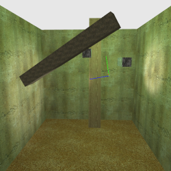
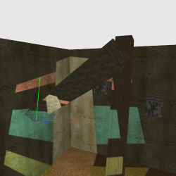
We implement spotlights via projected textures in the Projected Light project. This tutorial uses a similar scene to the one before, though with slightly different numbers for lighting. The main difference, scene wise, is the addition of a textured background box.
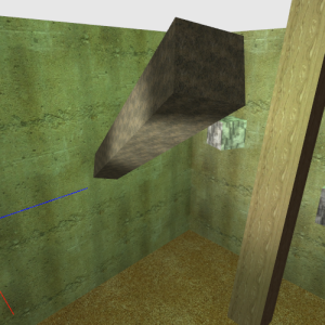
The camera controls work the same way as before. The projected flashlight, represented by the red, green, and blue axes, is moved with the IJKL keyboard keys, with O and U moving up and down, respectively. The right mouse button rotates the flashlight around; the blue line points in the direction of the light. The flashlight's position and orientation are built around the camera controls, so it rotates around a point in front of the flashlight. It translates relative to its current facing as well. As usual, holding down the Shift key will cause the flashlight to move more slowly.
Pressing the G key will toggle all of the regular lighting on and off. This makes it easier to see just the light from our projected texture.
Let us first look at how we achieve the projected texture effect. We want to take the model space positions of the vertices and project them onto the texture. However, there is one minor problem: the scene graph system provides a transform from model space into the visible camera space. We need a transform to our special projected texture camera space, which has a different position and orientation.
We resolve this by being clever. We already have positions in the viewing camera space. So we simply start there and construct a matrix from view camera space into our texture camera space.
Example 17.6. View Camera to Projected Texture Transform
glutil::MatrixStack lightProjStack;
//Texture-space transform
lightProjStack.Translate(0.5f, 0.5f, 0.0f);
lightProjStack.Scale(0.5f, 0.5f, 1.0f);
//Project. Z-range is irrelevant.
lightProjStack.Perspective(g_lightFOVs[g_currFOVIndex], 1.0f, 1.0f, 100.0f);
//Transform from main camera space to light camera space.
lightProjStack.ApplyMatrix(lightView);
lightProjStack.ApplyMatrix(glm::inverse(cameraMatrix));

g_lightProjMatBinder.SetValue(lightProjStack.Top());
Reading the modifications to lightProjStack in bottom-to-top
order, we begin by using the inverse of the view camera matrix. This transforms all
of our vertex positions back to world space, since the view camera matrix is a
world-to-camera matrix. We then apply the world-to-texture-camera matrix. This is
followed by a projection matrix, which uses an aspect ratio of 1.0. The last two
transforms move us from [-1, 1] NDC space to the [0, 1] texture space.
The zNear and zFar for the projection matrix are entirely irrelevant. They need to be legal values for your perspective matrix (strictly greater than 0, and zFar must be larger than zNear), but the values themselves are meaningless. We will discard the Z coordinate entirely later on.
We use a matrix uniform binder to associate that transformation matrix with all of the objects in the scene. This is all we need to do to set up the projection, as far as the matrix math is concerned.
Our vertex shader (projLight.vert) takes care of things in
the obvious way:
lightProjPosition = cameraToLightProjMatrix * vec4(cameraSpacePosition, 1.0);
Note that this line is part of the vertex shader;
lightProjPosition is passed to the fragment shader. One might
think that the projection would work best in the fragment shader, but doing it
per-vertex is actually just fine. The only time one would need to do the projection
per-fragment would be if one was using imposters or was otherwise modifying the
depth of the fragment. Indeed, because it works so well with a simple per-vertex
matrix transform, projected textures were once a preferred way of doing cheap
lighting in many situations.
In the fragment shader, projLight.frag, we want to use the
projected texture as a light. We have the ComputeLighting
function in this shader from prior tutorials. All we need to do is make our
projected light appear to be a regular light.
PerLight currLight;
currLight.cameraSpaceLightPos = vec4(cameraSpaceProjLightPos, 1.0);
currLight.lightIntensity =
    textureProj(lightProjTex, lightProjPosition.xyw) * 4.0;

currLight.lightIntensity = lightProjPosition.w > 0 ?
	currLight.lightIntensity : vec4(0.0);
We create a simple structure that we fill in. Later, we pass this structure to
ComputeLighting, and it does the usual thing.
The view camera space position of the projected light is passed in as a uniform. It is necessary for our flashlight to properly obey attenuation, as well as to find the direction towards the light.
The next line is where we do the actual texture projection. The
textureProj is a texture accessing function that does
projective texturing. Even though lightProjTex is a
sampler2D (for 2D textures), the texture coordinate has three
dimensions. All forms of textureProj take one extra texture
coordinate compared to the regular texture function. This extra
texture coordinate is divided into the previous one before being used to access the
texture. Thus, it performs the perspective divide for us.
Note
Mathematically, there is virtually no difference between using
textureProj and doing the divide ourselves and calling
texture with the results. While there may not be a
mathematical difference, there very well may be a performance difference. There
may be specialized hardware that does the division much faster than the
general-purpose opcodes in the shader. Then again, there may not. However, using
textureProj will certainly be no slower than
texture in the general case, so it's still a good
idea.
Notice that the value pulled from the texture is scaled by 4.0. This is done because the color values stored in the texture are clamped to the [0, 1] range. To bring it up to our high dynamic range, we need to scale the intensity appropriately.
The texture being projected is bound to a known texture unit globally; the scene graph already associates the projective shader with that texture unit. So there is no need to do any special work in the scene graph to make objects use the texture.
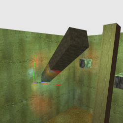
The last statement is special. It compares the W component of the interpolated position against zero, and sets the light intensity to zero if the W component is less than or equal to 0. What is the purpose of this?
It stops this from happening:
The projection math doesn't care what side of the center of projection an object is on; it will work either way. And since we do not actually do clipping on our texture projection, we need some way to prevent back projection from happening. We effectively need to do some form of clipping.
Recall that, given the standard perspective transform, the W component is the negation of the camera-space Z. Since the camera in our camera space is looking down the negative Z axis, all positions that are in front of the camera must have a W > 0. Therefore, if W is less than or equal to 0, then the position is behind the camera.
The size of the flashlight can be changed simply by modifying the field of view in the texture projection matrix. Pressing the Y key will increase the FOV, and pressing the N key will decrease it. An increase to the FOV means that the light is projected over a greater area. At a large FOV, we effectively have an entire hemisphere of light.
Another interesting trick we can play is to have multi-colored lights. Press the 2; this will change to a texture that contains spots of various different colors.
This kind of complex light emitter would not be possible without using a texture. Well it could be possible without textures, but it would require a lot more processing power than a few matrix multiplies, a division in the fragment shader, and a texture access. Press the 1 key to go back to the flashlight texture.
There is one final issue that can and will crop up with projected textures: what
happens when the texture coordinates are outside of the [0, 1] boundary. With
previous textures, we used either GL_CLAMP_TO_EDGE or
GL_REPEAT for the S and T texture coordinate wrap modes.
Repeat is obviously not a good idea here; thus far, our sampler objects have been
clamping to the texture's edge. That worked fine because our edge texels have all
been zero. To see what happens when they are not, press the 3
key.
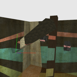
That rather ruins the effect. Fortunately, OpenGL does provide a way to resolve this. It gives us a way to say that texels fetched outside of the [0, 1] range should return a particular color. As before, this is set up with the sampler object:
Example 17.7. Border Clamp Sampler Objects
glSamplerParameteri(g_samplers[1], GL_TEXTURE_WRAP_S, GL_CLAMP_TO_BORDER);
glSamplerParameteri(g_samplers[1], GL_TEXTURE_WRAP_T, GL_CLAMP_TO_BORDER);

float color[4] = {0.0f, 0.0f, 0.0f, 1.0f};
glSamplerParameterfv(g_samplers[1], GL_TEXTURE_BORDER_COLOR, color);
The S and T wrap modes are set to GL_CLAMP_TO_BORDER. Then the
border's color is set to zero. To toggle between the edge clamping sampler and the
border clamping one, press the H key.
That's much better now.