Table of Contents
In this tutorial, we will look at how to deal with rendering multiple objects, as well as what happens when multiple objects overlap.
The first step in looking at what happens when objects overlap is to draw more than one object. This is an opportunity to talk about a concept that will be useful in the future.
An object, in terms of what you draw, can be considered the results of a single drawing call. Thus, an object is the smallest series of triangles that you draw with a single set of program object state.
Up until now, every time we have attempted to draw anything, we needed to do certain setup work before the draw call. In particular, we have to do the following, for each vertex attribute used by the vertex shader:
-
Use
glEnableVertexAttribArrayto enable this attribute. -
Use
glBindBuffer(GL_ARRAY_BUFFER) to bind to the context the buffer object that contains the data for this attribute. -
Use
glVertexAttribPointerto define the format of the data for the attribute within the buffer object previously bound toGL_ARRAY_BUFFER.
The more attributes you have, the more work you need to do for each object. To alleviate this burden, OpenGL provides an object that stores all of the state needed for rendering: the Vertex Array Object (VAO).
VAOs are created with the glGenVertexArray function. This
works like glGenBuffers (and like most other OpenGL objects);
you can create multiple objects with one call. As before, the objects are
GLuints.
VAOs are bound to the context with glBindVertexArray; this
function does not take a target the way that glBindBuffer does.
It only takes the VAO to bind to the context.
Once the VAO is bound, calls to certain functions change the data in the bound VAO. Technically, they always have changed the VAO's state; all of the prior tutorials have these lines in the initialization function:
glGenVertexArrays(1, &vao);
glBindVertexArray(vao);
This creates a single VAO, which contains the vertex array state that we have been setting. This means that we have been changing the state of a VAO in all of the tutorials. We just did not talk about it at the time.
The following functions change VAO state. Therefore, if no VAO is bound to the
context (if you call glBindVertexArray(0) or you do not bind a
VAO at all), all of these functions, except as noted, will fail.
-
glVertexAttribPointer. AlsoglVertexAttribIPointer, but we have not talked about that one yet. -
glEnableVertexAttribArray/glDisableVertexAttribArray -
glBindBuffer(GL_ELEMENT_ARRAY_BUFFER): Calling this without a VAO bound will not fail.
This allows you to setup a VAO early on, during initialization, and then simply bind it and call a rendering function to draw your object. Be advised when using a VAO in this way: VAOs are not immutable. Calling any of the above functions will change the data stored in the VAO.
In the last tutorial, we drew a rectangular prism. If you looked carefully at the vertex data, you may have noticed that a lot of vertex data was frequently repeated. To draw one face of the cube, we were required to have 6 vertices; the two shared vertices (along the shared line between the two triangles) had to be in the buffer object twice.
For a simple case like ours, this is only a minor increase in the size of the vertex data. The compact form of the vertex data could be 4 vertices per face, or 24 vertices total, while the expanded version we used took 36 total vertices. However, when looking at real meshes, like human-like characters and so forth that have thousands if not millions of vertices, sharing vertices becomes a major benefit in both performance and memory size. Removing duplicate data can shrink the size of the vertex data by 2x or greater in many cases.
In order to remove this extraneous data, we must perform indexed drawing, rather than the array drawing we have been doing up until now. In an earlier tutorial, we defined glDrawArrays conceptually as the following pseudo-code:
Example 5.1. Draw Arrays Implementation
void glDrawArrays(GLenum type, GLint start, GLint count)
{
    for(GLint element = start; element < start + count; element++)
    {
        VertexShader(positionAttribArray[element], colorAttribArray[element]);
    }
}
This defines how array drawing works. You start with a
particular index into the buffers, defined by the start
parameter, and proceed forward by count vertices.
In order to share attribute data between multiple triangles, we need some way to random-access the attribute arrays, rather than sequentially accessing them. This is done with an element array, also known as an index array.
Let's assume you have the following attribute array data:
  Position Array:  Pos0, Pos1, Pos2, Pos3
  Color Array:     Clr0, Clr1, Clr2, Clr3
You can use glDrawArrays to render either the first 3
vertices as a triangle, or the last 3 vertices as a triangle (using a
start of 1 and count of 3). However, with
the right element array, you can render 4 triangles from just these 4
vertices:
Element Array: 0, 1, 2, 0, 2, 3, 0, 3, 1, 1, 2, 3
This will cause OpenGL to generate the following sequence of vertices:
  (Pos0, Clr0), (Pos1, Clr1), (Pos2, Clr2),
  (Pos0, Clr0), (Pos2, Clr2), (Pos3, Clr3),
  (Pos0, Clr0), (Pos3, Clr3), (Pos1, Clr1),
  (Pos1, Clr1), (Pos2, Clr2), (Pos3, Clr3),
12 vertices, which generate 4 triangles.
Now that we understand how indexed drawing works, we need to know how to set it up in OpenGL. Indexed drawing requires two things: a properly-constructed element array and using a new drawing command to do the indexed drawing.
Element arrays, as you might guess, are stored in buffer objects. They have a
special buffer object binding point, GL_ELEMENT_ARRAY_BUFFER. You
can use this buffer binding point for normal maintenance of a buffer object
(allocating memory with glBufferData, etc), just like
GL_ARRAY_BUFFER. But it also has a special meaning to OpenGL:
indexed drawing is only possible when a buffer object is bound to this binding
point, and the element array comes from this buffer object.
Note
All buffer objects in OpenGL are the same, regardless of what target they are bound to; buffer objects can be bound to multiple targets. So it is perfectly legal to use the same buffer object to store vertex attributes and element arrays (and, FYI, any data for any other use of buffer objects that exists in OpenGL). Obviously, the different data would be in separate regions of the buffer.
In order to do indexed drawing, we must bind the buffer to
GL_ELEMENT_ARRAY_BUFFER and then call
glDrawElements.
void glDrawElements( | GLenum mode, |
| GLsizei count, | |
| GLenum type, | |
GLsizeiptr indices); |
The first parameter is the same as the first parameter of glDrawArrays. The
count parameter defines how many indices will be pulled
from the element array. The type field defines what the basic
type of the indices in the element array are. For example, if the indices are stored
as 16-bit unsigned shorts (GLushort), then this field should be
GL_UNSIGNED_SHORT. This allows the user the freedom to use
whatever size of index they want. GL_UNSIGNED_BYTE and
GL_UNSIGNED_INT (32-bit) are also allowed; indices must be
unsigned.
The last parameter is the byte-offset into the element array at which the index
data begins. Index data (and vertex data, for that matter) should always be aligned
to its size. So if we are using 16-bit unsigned shorts for indices, then
indices should be an even number.
This function can be defined by the following pseudo-code:
Example 5.2. Draw Elements Implementation
GLvoid *elementArray;

void glDrawElements(GLenum type, GLint count, GLenum type, GLsizeiptr indices)
{
    GLtype *ourElementArray = (type*)((GLbyte *)elementArray + indices);

    for(GLint elementIndex = 0; elementIndex < count; elementIndex++)
    {
        GLint element = ourElementArray[elementIndex];
        VertexShader(positionAttribArray[element], colorAttribArray[element]);
    }
}
The elementArray represents the buffer object bound to
GL_ELEMENT_ARRAY_BUFFER.
The tutorial project Overlap No Depth uses VAOs to draw two separate objects. These objects are rendered using indexed drawing. The setup for this shows one way to have the attribute data for multiple objects stored in a single buffer.
For this tutorial, we will be drawing two objects. They are both wedges, with the sharp end facing the viewer. The difference between them is that one is horizontal and the other is vertical on the screen.
The shaders are essentially unchanged from before. We are using the perspective matrix shader from the last tutorial, with modifications to preserve the aspect ratio of the scene. The only difference is the pre-camera offset value; in this tutorial, it is a full 3D vector, which allows us to position each wedge in the scene.
The initialization has changed, allowing us to create our VAOs once at start-up time, then use them to do the rendering. The initialization code is as follows:
Example 5.3. VAO Initialization
void InitializeVertexArrayObjects()
{
    glGenVertexArrays(1, &vaoObject1);
    glBindVertexArray(vaoObject1);

    size_t colorDataOffset = sizeof(float) * 3 * numberOfVertices;

    glBindBuffer(GL_ARRAY_BUFFER, vertexBufferObject);
    glEnableVertexAttribArray(0);
    glEnableVertexAttribArray(1);
    glVertexAttribPointer(0, 3, GL_FLOAT, GL_FALSE, 0, 0);
    glVertexAttribPointer(1, 4, GL_FLOAT, GL_FALSE, 0, (void*)colorDataOffset);
    glBindBuffer(GL_ELEMENT_ARRAY_BUFFER, indexBufferObject);

    glBindVertexArray(0);

    glGenVertexArrays(1, &vaoObject2);
    glBindVertexArray(vaoObject2);

    size_t posDataOffset = sizeof(float) * 3 * (numberOfVertices/2);
    colorDataOffset += sizeof(float) * 4 * (numberOfVertices/2);

    //Use the same buffer object previously bound to GL_ARRAY_BUFFER.
    glEnableVertexAttribArray(0);
    glEnableVertexAttribArray(1);
    glVertexAttribPointer(0, 3, GL_FLOAT, GL_FALSE, 0, (void*)posDataOffset);
    glVertexAttribPointer(1, 4, GL_FLOAT, GL_FALSE, 0, (void*)colorDataOffset);
    glBindBuffer(GL_ELEMENT_ARRAY_BUFFER, indexBufferObject);

    glBindVertexArray(0);
}
This code looks complicated, but it is really just the rendering code we have seen
before. The offset computations for the glVertexAttribPointer
calls are more complex, due to having the data for 2 objects stored in a single
buffer. But overall it is the same code.
The code generates 2 VAOs, binds them, then sets their state. Recall that, while
the GL_ARRAY_BUFFER binding is not part of the VAOs state, the
GL_ELEMENT_ARRAY_BUFFER binding is part
of that state. So these VAOs store the attribute array data and the element buffer
data; everything necessary to render each object except for the actual drawing
call.
In this case, both objects use the same element buffer. However, since the element
buffer binding is part of the VAO state, it must be set into
each VAO individually. Notice that we only set the
GL_ARRAY_BUFFER binding once, but the
GL_ELEMENT_ARRAY_BUFFER is set for each VAO.
Note
If you look at the vertex position attribute in our array, we have a 3-component position vector. But the shader still uses a vec4. This works because OpenGL will fill in any missing vertex attribute components that the shader looks for but the attribute array doesn't provide. It fills them in with zeros, except for the fourth component, which is filled in with a 1.0.
Though the initialization code has been expanded, the rendering code is quite simple:
Example 5.4. VAO and Indexed Rendering Code
    glClearColor(0.0f, 0.0f, 0.0f, 0.0f);
    glClear(GL_COLOR_BUFFER_BIT);

    glUseProgram(theProgram);

    glBindVertexArray(vaoObject1);
    glUniform3f(offsetUniform, 0.0f, 0.0f, 0.0f);
    glDrawElements(GL_TRIANGLES, ARRAY_COUNT(indexData), GL_UNSIGNED_SHORT, 0);

    glBindVertexArray(vaoObject2);
    glUniform3f(offsetUniform, 0.0f, 0.0f, -1.0f);
    glDrawElements(GL_TRIANGLES, ARRAY_COUNT(indexData), GL_UNSIGNED_SHORT, 0);

    glBindVertexArray(0);
    glUseProgram(0);

    glutSwapBuffers();
    glutPostRedisplay();
We bind a VAO, set its uniform data (in this case, to position the object
properly), and then we draw it with a call to glDrawElements.
This step is repeated for the second object.
Running this tutorial will show the following image:
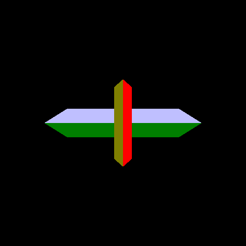
The two objects are essentially flipped versions of the same one, a wedge. One object appears smaller than the other because it is farther away, in terms of its Z distance to the camera. We are using a perspective transform, so it make sense that more distant objects appear smaller. However, if the smaller object is behind the larger one, why is it rendered on top of the one in front?
Before we solve this mystery, there is one minor issue we should cover first.