Table of Contents
Thus far, we have seen very flat things. Namely, a single triangle. Maybe the triangle moved around or had some colors.
This tutorial is all about how to create a realistic world of objects.
The Orthographic Cube tutorial renders a rectangular prism (a 3D rectangle). The dimensions of the prism are 0.5x0.5x1.5, so it is longer in the Z axis by 3x the X and Y.
The code in this tutorial should be familiar, for the most part. We simply draw 12 triangles rather than one. The rectangular faces of the prism are made of 2 triangles, splitting the face along one of the diagonals.
The vertices also have a color. However, the color for the 6 vertices that make up a face is always the same; this gives each face a single, uniform color.
The vertex shader is a combination of things we know. It passes a color through to the fragment stage, but it also takes a vec2 offset uniform that it adds an offset to the X and Y components of the position. The fragment shader simply takes the interpolated color and uses it as the output color.
There is one very noteworthy code change, however: the initialization routine. It has a few new functions that need to be discussed.
Example 4.1. Face Culling Initialization
void init()
{
    InitializeProgram();
    InitializeVertexBuffer();

    glGenVertexArrays(1, &vao);
    glBindVertexArray(vao);

    glEnable(GL_CULL_FACE);
    glCullFace(GL_BACK);
    glFrontFace(GL_CW);
}
The last three lines are new.
The glEnable function is a multi-purpose tool. There are a
lot of binary on/off flags that are part of OpenGL's state.
glEnable is used to set these flags to the
“on” position. Similarly, there is a glDisable
function that sets the flag to “off.”
The GL_CULL_FACE flag, when enabled, tells OpenGL to activate
face culling. Up until now, we have been rendering with
face culling off.
Face culling is a useful feature for saving performance. Take our rectangular prism, for example. Pick up a remote control; their general shape is that of a rectangular prism. No matter how you look at it or orient it, you can never see more than 3 sides of it at once. So why bother spending all that fragment processing time drawing the other three sides?
Face culling is a way of telling OpenGL not to draw the sides of an object that you cannot see. It is quite simple, really.
In window space, after the transform from normalized device coordinates, you have a triangle. Each vertex of that triangle was presented to OpenGL in a specific order. This gives you a way of numbering the vertices of the triangle.
No matter what size or shape the triangle is, you can classify the ordering of a triangle in two ways: clockwise or counter-clockwise. That is, if the order of the vertices from 1 to 2 to 3 moves clockwise in a circle, relative to the triangle's center, then the triangle is facing clockwise relative to the viewer. Otherwise, the triangle is counter-clockwise relative to the viewer. This ordering is called the winding order.
Figure 4.1. Triangle Winding Order

The left triangle has a clockwise winding order; the triangle on the right has a counter-clockwise winding order.
Face culling in OpenGL works based on this ordering. Setting this is a two-step process, and is accomplished by the last two statements of the initialization function.
The glFrontFace defines which winding order, clockwise or
counter-clockwise, is considered to be the “front” side of the
triangle. This function can be given either GL_CW or
GL_CCW, for clockwise and counter-clockwise
respectively.
The glCullFace function defines which side, front or back,
gets culled. This can be given GL_BACK,
GL_FRONT, or GL_FRONT_AND_BACK. The latter
culls everything, so no triangles are rendered. This can be
useful for measuring vertex shader performance but is less useful for actually
drawing anything.
The triangle data in the tutorial is specifically ordered so that the clockwise facing of the triangles face out. This prevents the drawing of the rear-facing faces.
So, the image looks like this:
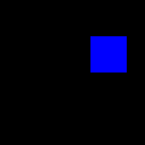
There's something wrong with this. Namely, that it looks like a square.
Pick up a remote control again. Point it directly at your eye and position it so that it is in the center of your vision. You should only be able to see the front panel of the remote.
Now, move it to the right and up, similar to where the square is. You should be able to see the bottom and left side of the remote.
So we should be able to see the bottom and left side of our rectangular prism. But we cannot. Why not?
Think back to how rendering happens. In clip-space, the vertices of the back end of the rectangular prism are directly behind the front end. And when we transform these into window coordinates, the back vertices are still directly behind the front vertices. This is what the rasterizer sees, so this is what the rasterizer renders.
There has to be something that reality is doing that we are not. That something is called “perspective.”