Recall that our destination image, the screen, is just a two dimensional array of pixels. The 3D rendering pipeline we are using defines transformations of vertex positions that go from clip-space to window space. Once the positions are in window space, 2D triangles are rendered.
A projection, in terms of the rendering pipeline is a way to transform a world from one dimensionality to another. Our initial world is three dimensional, and therefore, the rendering pipeline defines a projection from this 3D world into the 2D one that we see. It is the 2D world in which the triangles are actually rendered.
Finite projections, which are the ones we are interested in, only project objects onto a finite space of the lower dimensionality. For a 3D-to-2D projection, there is a finite plane on which the world is projected. For 2D to 1D, there is a bounded line that is the result of the projection.
An orthographic projection is a very simplistic projection. When projecting onto an axis-aligned surface, as below, the projection simply involves throwing away the coordinate perpendicular to the surface.
Figure 4.3. 2D to 1D Orthographic Projection

A scene orthographically projected onto the black line. The gray box represents the part of the world that is visible to the projection; parts of the scene outside of this region are not seen.
When projecting onto an arbitrary line, the math is a bit more complicated. But what makes it an orthographic projection is that the dimension perpendicular to the surface is negated uniformly to create the projection. The fact that it is a projection in the direction of the perpendicular and that it is uniform is what makes it orthographic.
Human eyes do not see the world via orthographic projection. If they did, you would only be able to see an area of the world the size of your pupils. Because we do not use orthographic projections to see (among other reasons), orthographic projections do not look particularly real to us.
Instead, we use a pinhole camera model for our eyesight. This model performs a perspective projection. A perspective projection is a projection of the world on a surface as though seen through a single point. A 2D to 1D perspective projection looks like this:

As you can see, the projection is radial, based on the location of a particular point. That point is the eye or camera of the projection.
Just from the shape of the projection, we can see that the perspective projection causes a larger field of geometry to be projected onto the surface. An orthographic projection only captures the rectangular prism directly in front of the surface of projection. A perspective projection captures a larger space of the world.
In 2D, the shape of the perspective projection is a regular trapezoid (a quadrilateral that has only one pair of parallel sides, and the other pair of sides have the same slope). In 3D, the shape is called a frustum; essentially, a pyramid with the tip chopped off.

Now that we know what we want to do, we just need to know how to do it.
We will be making a few simplifying assumptions:
-
The plane of projection is axis-aligned and faces down the -Z axis. Thus, -Z is farther away from the plane of projection.
-
The eye point is fixed at the origin (0, 0, 0).
-
The size of the plane of projection will be [-1, 1]. All points that project outside of this range are not drawn.
Yes, this sounds somewhat like normalized device coordinate space. No, that's not a coincidence. But let's not get ahead of ourselves.
We know a few things about how the projection results will work. A perspective projection essentially shifts vertices towards the eye, based on the location of that particular vertex. Vertices farther in Z from the front of the projection are shifted less than those closer to the eye. And the shift also depends on how far the vertices are from the center of the plane of projection, in the X,Y direction.
The problem is really just a simple geometry problem. Here is the equivalent form in a 2D to 1D perspective projection.
Figure 4.6. 2D to 1D Perspective Projection Diagram

The projection of the point P onto the projection plane. This plane is at an offset of Ez compared to the eye point, which is fixed at the origin. R is the projected point.
What we have are two similar right triangles: the triangle formed by E, R and Ez, and the triangle formed by E, P, and Pz. We have the eye position and the position of the unprojected point. To find the location of R, we simply do this:
Since this is a vectorized function, this solution applies equally to 2D as to 3D. Thus, perspective projection is simply the task of applying that simple formula to every vertex that the vertex shader receives.
The basic perspective projection function is simple. Really simple. Indeed, it is so simple that it has been built into graphics hardware since the days of the earliest 3Dfx card and even prior graphics hardware.
You might notice that the scaling can be expressed as a division operation (multiplying by the reciprocal). And you may recall that the difference between clip space and normalized device coordinate space is a division by the W coordinate. So instead of doing the divide in the shader, we can simply set the W coordinate of each vertex correctly and let the hardware handle it.
This step, the conversion from clip-space to normalized device coordinate space, has a particular name: the perspective divide. So named because it is usually used for perspective projections; orthographic projections tend to have the W coordinates be 1.0, thus making the perspective divide a no-op.
Note
You may be wondering why this arbitrary division-by-W step exists. You may also be wondering, in this modern day of vertex shaders that can do vector divisions very quickly, why we should bother to use the hardware division-by-W step at all. There are several reasons. One we will cover in just a bit when we deal with matrices. More important ones will be covered in future tutorials. Suffice it to say that there are very good reasons to put the perspective term in the W coordinate of clip space vertices.
Before we can actually implement perspective projection, we need to deal with a new issue. The orthographic projection transform was essentially a no-op. It is automatic, by the nature of how OpenGL uses the clip space vertices output by the vertex shader. The perspective projection transform is a bit more involved. Indeed, it fundamentally changes the nature of the world.
Our vertex positions before now have been stored directly in clip space. We did on occasion add an offset to the positions to move them to more convenient locations. But for all intents and purposes, the position values stored in the buffer object are exactly what our vertex shader outputs: clip space positions.
Recall that the divide-by-W is part of the OpenGL-defined transform from clip space positions to NDC positions. Perspective projection defines a process for transforming positions into clip space, such that these clip space positions will appear to be a perspective projection of a 3D world. This transformation has well-defined outputs: clip space positions. But what exactly are its input values?
We therefore define a new space for positions; let us call this space camera space.[3] This is not a space that OpenGL recognizes (unlike clip-space which is explicitly defined by GL); it is purely an arbitrary user construction. The definition of camera space will affect the exact process of perspective projection, since that projection must produce proper clip space positions. Therefore, it can be useful to define camera space based on what we know of the general process of perspective projection. This minimizes the differences between camera space and the perspective form of clip space, and it can simplify our perspective projection logic.
The volume of camera space will range from positive infinity to negative infinity in all directions. Positive X extends right, positive Y extends up, and positive Z is forward. The last one is a change from clip space, where positive Z is away.
Our perspective projection transform will be specific to this space. As previously stated, the projection plane shall be a region [-1, 1] in the X and Y axes, and at a Z value of -1. The projection will be from vertices in the -Z direction onto this plane; vertices that have a positive Z value are behind the projection plane.
Now, we will make one more simplifying assumption: the location of the center of the perspective plane is fixed at (0, 0, -1) in camera space. Therefore, since the projection plane is pointing down the -Z axis, the eye's location relative to the plane of projection is (0, 0, -1). Thus, the Ez value, the offset from the projection plane to the eye, is always -1. This means that our perspective term, when phrased as division rather than multiplication, is simply Pz/-1: the negation of the camera-space Z coordinate.
Having a fixed eye position and projection plane makes it difficult to have zoom-in/zoom-out style effects. This would normally be done by moving the plane relative to the fixed eye point. There is a way to do this, however. All you need to do is, when transforming from camera space to clip space, scale all of the X and Y values by a constant. What this does is make the world, as the camera sees it, smaller or larger in the X and Y axes. It effectively makes the frustum wider or narrower.
To compare, camera space and normalized device coordinate space (after the perspective divide) look like this, using a 2D version of a perspective projection:
Do note that this diagram has the Z axis flipped from camera space and normalized device coordinate (NDC) space. This is because camera space and NDC space have different viewing directions. In camera space, the camera looks down the -Z axis; more negative Z values are farther away. In NDC space, the camera looks down the +Z axis; more positive Z values are farther away. The diagram flips the axis so that the viewing direction can remain the same between the two images (up is away).
If you perform an orthographic projection from NDC space on the right (by dropping the Z coordinate), then what you get is a perspective projection of the world on the left. In effect, what we have done is transform objects into a three-dimensional space from which an orthographic projection will look like a perspective one.
So we know what to do with the X and Y coordinates. But what does the Z value mean in a perspective projection?
Until the next tutorial, we are going to ignore the meaning of Z. Even so, we still need some kind of transform for it; if a vertex extends outside of the [-1, 1] box in any axis in normalized device coordinate (NDC) space, then it is outside of the viewing area. And because the Z coordinate undergoes the perspective divide just like the X and Y coordinates, we need to take this into account if we actually want to see anything in our projection.
Our W coordinate will be based on the camera-space Z coordinate. We need to map Z values from the camera-space range [0, -∞) to the NDC space range [-1, 1]. Since camera space is an infinite range and we're trying to map to a finite range, we need to do some range bounding. The frustum is already finitely bound in the X and Y directions; we simply need to add a Z boundary.
The maximum distance that a vertex can be before it is considered no longer in view is the camera zFar. We also have a minimum distance from the eye; this is called the camera zNear. This creates a finite frustum for our camera space viewpoint.
Note
It is very important to remember that these are the zNear and zFar for the camera space. The next tutorial will also introduce a range of depth, also using the names zNear and zFar. This is a related but fundamentally different range.
The camera zNear can appear to effectively determine the offset between the eye and the projection plane. However, this is not the case. Even if zNear is less than 1, which would place the near Z plane behind the projection plane, you still get an effectively valid projection. Objects behind the plane can be projected onto the plane just as well as those in front of it; it is still a perspective projection. Mathematically, this works.
What it does not do is what you would expect if you moved the plane of projection. Since the plane of projection has a fixed size (the range [-1, 1]), moving the plane would alter where points appear in the projection. Changing the camera zNear does not affect the X, Y position of points in the projection.
There are several ways to go about mapping one finite range to another. One confounding problem is the perspective divide itself; it is easy to perform a linear mapping between two finite spaces. It is quite another to do a mapping that remains linear after the perspective divide. Since we will be dividing by -Z itself (the camera-space Z, not the clip-space Z), the math is much more complex than you might expect.
For reasons that will be better explained in the next tutorial, we will use this modestly complicated function to compute the clip-space Z:
Some important things about this equation and camera zNear/zFar. First, these values are positive; the equation accounts for this when performing the transformation. Also, zNear cannot be 0; it can be very close to zero, but it must never be exactly zero.
Let us review the previous diagram of camera-to-NDC transformation in 2D space:

The example of 2D camera-space vs. 2D NDC space uses this equation to compute the Z values. Take a careful look at how the Z coordinates match. The Z distances are evenly spaced in camera space, but in NDC space, they are non-linearly distributed. And yet simultaneously, points that are colinear in camera-space remain colinear in NDC space.
This fact has some interesting properties that we will investigate further in the next tutorial.
Given all of the above, we now have a specific sequence of steps to transform a vertex from camera space to clip space. These steps are as follows:
-
Frustum adjustment: multiply the X and Y value of the camera-space vertices by a constant.
-
Depth adjustment: modify the Z value from camera space to clip space, as above.
-
Perspective division term: compute the W value, where Ez is -1.
Now that we have all the theory down, we are ready to put things properly in perspective. This is done in the ShaderPerspective tutorial.
Our new vertex shader, data\ManualPerspective.vert looks like
this:
Example 4.2. ManualPerspective Vertex Shader
#version 330

layout(location = 0) in vec4 position;
layout(location = 1) in vec4 color;

smooth out vec4 theColor;

uniform vec2 offset;
uniform float zNear;
uniform float zFar;
uniform float frustumScale;

void main()
{
    vec4 cameraPos = position + vec4(offset.x, offset.y, 0.0, 0.0);
    vec4 clipPos;

    clipPos.xy = cameraPos.xy * frustumScale;

    clipPos.z = cameraPos.z * (zNear + zFar) / (zNear - zFar);
    clipPos.z += 2 * zNear * zFar / (zNear - zFar);

    clipPos.w = -cameraPos.z;

    gl_Position = clipPos;
    theColor = color;
}
We have a few new uniforms, but the code itself is only modestly complex.
The first statement simply applies an offset, just like the vertex shaders we have seen before. It positions the object in camera space, so that it is offset from the center of the view. This is here to make it easier to position the object for projection.
The next statement performs a scalar multiply of the camera-space X and Y positions, storing them in a temporary 4-dimensional vector. From there, we compute the clip Z position based on the formula discussed earlier.
The W coordinate of the clip space position is the Z distance in camera space divided by the Z distance from the plane (at the origin) to the eye. The eye is fixed at (0, 0, -1), so this leaves us with the negation of the camera space Z position. OpenGL will automatically perform the division for us.
After that, we simply store the clip space position where OpenGL needs it, store the color, and we're done. The fragment shader is unchanged.
With all of the new uniforms, our program initialization routine has changed:
Example 4.3. Program Initialization
offsetUniform = glGetUniformLocation(theProgram, "offset");

frustumScaleUnif = glGetUniformLocation(theProgram, "frustumScale");
zNearUnif = glGetUniformLocation(theProgram, "zNear");
zFarUnif = glGetUniformLocation(theProgram, "zFar");

glUseProgram(theProgram);
glUniform1f(frustumScaleUnif, 1.0f);
glUniform1f(zNearUnif, 1.0f);
glUniform1f(zFarUnif, 3.0f);
glUseProgram(0);
We only set the new uniforms once. The scale of 1.0 means effectively no change. We define the Z to go from -1 to -3 (remember that, in our Z equation, the zNear and zFar are positive but refer to negative values).
The location of the prism has also changed. In the original tutorial, it was located on the 0.75 range in Z. Because camera space has a very different Z from clip space, this had to change. Now, the Z location of the prism is between -1.25 and -2.75.
All of this leaves us with this result:
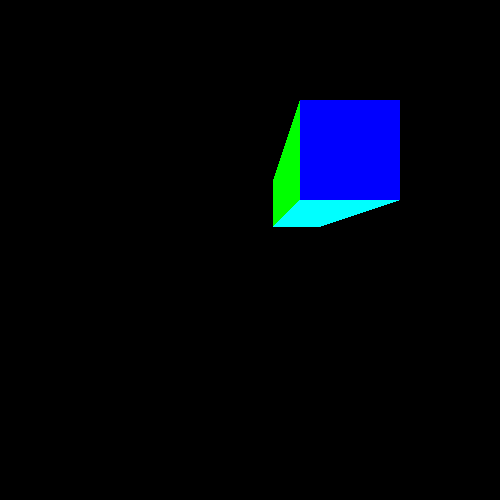
Now, it looks like a rectangular prism. A bright, colorful, unrealistic one.
We glossed over something in the vertex shader that bears more discussion. Namely, this line:
clipPos.xy = cameraPos.xy * frustumScale;
Even if you are familiar with vector math libraries in other languages, this code
should be rather odd. Traditional vector libraries allow you to write selectors like
vec.x and vec.w in order to get a specific
field from a vector. So what does something like vec.xy
mean?
Well, it means the obvious; this expression returns a 2D vector
(vec2), since there are only two components mentioned (X and Y). This
vector will have its first component come from the X component of
vec and the second component come from the Y component of
vec. This kind of selection is called, in GLSL parlance,
swizzle selection. The size of the returned vector will
be the number of components you mention, and the order of these components will
dictate the order of the components returned.
You can do any kind of swizzle operation on a vector, so long as you keep in mind the following rules:
-
You cannot select components that are not in the source vector. So if you have:
vec2 theVec;
You cannot do
theVec.zzbecause it has no Z component. -
You cannot select more than 4 components.
These are the only rules. So you can have a vec2 that you swizzle to
create a vec4 (vec.yyyx); you can repeat components;
etc. Anything goes so long as you stick to those rules.
You should also assume that swizzling is fast. This is not true of most CPU-based vector hardware, but since the earliest days of programmable GPUs, swizzle selection has been a prominent feature. In the early programmable days, swizzles caused no performance loss; in all likelihood, this has not changed.
Swizzle selection can also be used on the left side of the equals, as we have done here. It allows you to set specific components of a vector without changing the other components.
When you multiply a vector by a scalar (non-vector value), it does a component-wise multiply, returning a vector containing the scalar multiplied by each of the components of the vector. We could have written the above line as follows:
clipPos.x = cameraPos.x * frustumScale;
clipPos.y = cameraPos.y * frustumScale;
But it probably would not be as fast as the swizzle and vector math version.