A rotation transformation is the result of the orientation of the initial space being different from the orientation of the destination space. The basis vectors of the space do not change orientation relative to one another, but relative to the destination coordinate system, they are pointed in different directions than they were in their own coordinate system.
A rotation looks like this:

Rotations are usually considered the most complex of the basic transformations, primarily because of the math involved in computing the transformation matrix. Generally, rotations are looked at as an operation, such as rotating around a particular basis vector or some such. The prior part of the tutorial laid down some of the groundwork that will make this much simpler.
First, let's look back at our equation for determining what the position of a coordinate is relative to certain coordinate space:
Does not this look a bit familiar? No? Maybe this look at vector-matrix multiplication will jog your memory:
Still nothing? Perhaps an alternate look would help:
Does it look familiar now?
What this tells us is that the columns of our transformation matrices are, and have always been, nothing more than the axes of a coordinate system. Except for the fourth column; because the input position has a 1 in the W, it acts as an offset.
Transformation from one space to another ultimately means this: taking the basis vectors and origin point from the original coordinate system and re-expressing them relative to the destination coordinate system. The transformation matrix from one space to another contains the basis vectors and origin of the original coordinate system, but the values of those basis vectors and origin are relative to the destination coordinate system.
Earlier, we said that numerical coordinates of a space must be expressed relative to another space. A matrix is a numerical representation of a coordinate system, and its values are expressed in the destination coordinate system. Therefore, a transformation matrix takes values in one coordinate system and transforms them into another. It does this by taking the basis vectors and origin of the input coordinate system and represents them relative to the output space. To put it another way, the transformation from space A to space B is what space A looks like from an observer in space B.
A rotation matrix is just a transform that expresses the basis vectors of the input space in a different orientation. The length of the basis vectors will be the same, and the origin will not change. Also, the angle between the basis vectors will not change. All that changes is the relative direction of all of the basis vectors.
Therefore, a rotation matrix is not really a “rotation” matrix; it is an orientation matrix. It defines the orientation of one space relative to another space. Remember this, and you will avoid many pitfalls when you start dealing with more complex transformations.
For any two spaces, the orientation transformation between them can be expressed as rotating the source space by some angle around a particular axis (specified in the initial space). This is true for any change of orientation.
A common rotation question is to therefore compute a rotation around an arbitrary axis. Or to put it more correctly, to determine the orientation of a space if it is rotated around an arbitrary axis. The axis of rotation is expressed in terms of the initial space. In 2D, there is only one axis that can be rotated around and still remain within that 2D plane: the Z-axis.
In 3D, there are many possible axes of rotation. It does not have to be one of the initial space's basis axes; it can be any arbitrary direction. Of course, the problem is made much simpler if one rotates only around the primary axes.
Deriving these matrix equations is beyond the scope of this tutorial; so instead, we will simply provide them. To perform rotations along the primary axes, use the following matrices:
When using the standard C/C++ library sin and
cos functions, the angles must be in radians.
As useful as these are, the more generic equation for rotation by an angle about an arbitrary axis is as follows.
All of these matrices are such that, from the point of view of an observer looking down the axis of rotation (the positive direction of the axis is pointed into the eye of the observer), the object rotates counter-clockwise with positive angles.
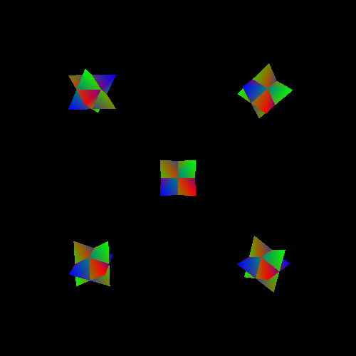
The Rotations tutorial shows off each of these rotation matrix functions. Similar to how the others work, there are multiple instances rendered based on functions.
The function that builds the transformation matrix looks like this:
Example 6.4. Rotation Transformation Building
glm::mat4 ConstructMatrix(float fElapsedTime)
{
    const glm::mat3 &rotMatrix = CalcRotation(fElapsedTime);
    glm::mat4 theMat(rotMatrix);
    theMat[3] = glm::vec4(offset, 1.0f);

    return theMat;
}
The constructor of glm::mat4 that takes a glm::mat3 generates a 4x4 matrix with the 3x3 matrix in the top-left corner, and all other positions 0 except the bottom-left corner, which is set to 1. As with much of GLM, this works in GLSL as well.