Thus far, our lighting examples have been fairly prosaic. A single light source illuminating a simple object hovering above flat terrain. This tutorial will demonstrate how to use multiple lights among a larger piece of terrain in a dynamic lighting environment. We will demonstrate how to properly light a scene. This is less about the artistic qualities of how a scene should look and more about how to make a scene look a certain way if that is how you desire it to look.
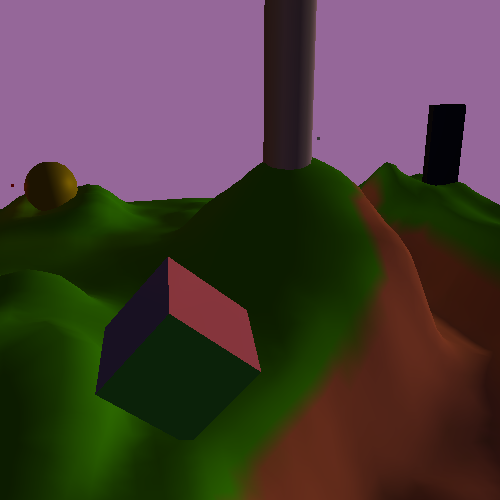
The intent for this scene is to be dynamic. The terrain will be large and hilly, unlike the flat plain we've seen in previous tutorials. It will use vertex colors where appropriate to give it terrain-like qualities. There will also be a variety of objects on the terrain, each with its own set of reflective characteristics. This will help show off the dynamic nature of the scene.
The very first step in lighting a scene is to explicitly detail what you want; without that, you're probably not going to find your way there. In this case, the scene is intended to be outdoors, so there will be a single massive directional light shining down. There will also be a number of smaller, weaker lights. All of these lights will have animated movement.
The biggest thing here is that we want the scene to dynamically change lighting levels. Specifically, we want a full day/night cycle. The sun will sink, gradually losing intensity until it has none. There, it will remain until the dawn of the next day, where it will gain strength and rise again. The other lights should be much weaker in overall intensity than the sun.
One thing that this requires is a dynamic ambient lighting range. Remember that the ambient light is an attempt to resolve the global illumination problem: that light bounces around in a scene and can therefore come from many sources. When the sun is at full intensity, the ambient lighting of the scene should be bright as well. This will mean that surfaces facing away from the sunlight will still be relatively bright, which is the case we see outside. When it is night, the ambient light should be virtually nil. Only surfaces directly facing one of the lights should be illuminated.
The Scene Lighting tutorial demonstrates the first version of attempting to replicate this scene.
The camera is rotated and zoomed as in prior tutorials. Where this one differs is that the camera's target point can be moved. The W, A, S, and D keys move the cameras forward/backwards and left/right, relative to the camera's current orientation. The Q and E keys raise and lower the camera, again relative to its current orientation. Holding Shift with these keys will move in smaller increments. You can toggle viewing of the current target point by pressing T.
Because the lighting in this tutorial is very time based, there are specialized controls for playing with time. There are two sets of timers: one that controls the sun's position (as well as attributes associated with this, like the sun's intensity, ambient intensity, etc), and another set of timers that control the positions of other lights in the scene. Commands that affect timers can affect the sun only, the other lights only, or both at the same time.
To have timer commands affect only the sun, press 2. To have timer commands affect only the other lights, press 3. To have timer commands affect both, press 1.
To rewind time by one second (of real-time), press the - key. To jump forward one second, press the = key. To toggle pausing, press the p key. These commands only affect the currently selected timers. Also, pressing the SpaceBar will print out the current sun-based time, in 24-hour notation.
The source code for this tutorial is much more complicated than prior ones. Due to
this complexity, it is spread over several files. All of the tutorial projects for
this tutorial share the Scene.h/cpp and
Lights.h/cpp files. The Scene files set up the objects in
the scene and render them. This file contains the surface properties of the
objects.
A lighting function requires two specific sets of parameters: values that
represent the light, and values that represent the surface. Surface properties are
often called material properties. Each object has its own
material properties, as defined in Scene.cpp.
The scene has 6 objects: the terrain, a tall cylinder in the middle, a
multicolored cube, a sphere, a spinning tetrahedron, and a mysterious black obelisk.
Each object has its own material properties defined by the
GetMaterials function.
These properties are all stored in a uniform buffer object. We have seen these before for data that is shared among several programs; here, we use it to quickly change sets of values. These material properties do not change with time; we set them once and do not change them ever again. This is primarily for demonstration purposes, but it could have a practical effect.
Each object's material data is defined as the following struct:
Example 12.1. Material Uniform Block
//GLSL
layout(std140) uniform;

uniform Material
{
    vec4 diffuseColor;
    vec4 specularColor;
    float specularShininess;
} Mtl;
//C++
struct MaterialBlock
{
    glm::vec4 diffuseColor;
    glm::vec4 specularColor;
    float specularShininess;
    float padding[3];
};
The padding variable in the C++ definition represents the fact
that the GLSL definition of this uniform block will be padded out to a size of 12
floats. This is due to the nature of “std140” layout (feel free to read
the appropriate section in the OpenGL specification to see why). Note the global
definition of “std140” layout; this sets all uniform blocks to use
“std140” layout unless they specifically override it. That way, we
do not have to write “layout(std140)” for each of the three uniform
blocks we use in each shader file.
Also, note the use of Mtl at the foot of the uniform block
definition. This is called the instance name of an interface
block. When no instance name is specified, then the names in the uniform block are
global. If an instance name is specified, this name must be used to qualify access
to the names within that block. This allows us to have the in vec4
diffuseColor be separate from the material definition's
Mtl.diffuseColor.
What we want to do is put 6 material blocks in a single uniform buffer. One might
naively think that one could simply allocate a buffer object 6 times the
sizeof(MaterialBlock), and simply store the data as a C++
array. Sadly, this will not work due to a UBO limitation.
When you use glBindBufferRange to bind a UBO, OpenGL requires
that the offset parameter, the parameter that tells where the beginning of the
uniform block's data is within the buffer object, be aligned to a specific value.
That is, the begining of a uniform block within a uniform buffer must be a multiple
of a specific value. 0 works, of course, but since we have more than one block
within a uniform buffer, they cannot all start at the buffer's beginning.
What is this value, you may ask? Welcome to the world of implementation-dependent values. This means that it can (and most certainly will) change depending on what platform you're running on. This code was tested on two different hardware platforms; one has a minimum alignment of 64, the other an alignment of 256.
To retrieve the implementation-dependent value, we must use a previously-unseen
function: glGetIntegerv. This is a function that does one
simple thing: gets integer values from OpenGL. However, the meaning of the value
retrieved depends on the enumerator passed as the first parameter. Basically, it's a
way to have state retrieval functions that can easily be extended by adding new
enumerators rather than new functions.
The code that builds the material uniform buffer is as follows:
Example 12.2. Material UBO Construction
int uniformBufferAlignSize = 0;
glGetIntegerv(GL_UNIFORM_BUFFER_OFFSET_ALIGNMENT, &uniformBufferAlignSize);

m_sizeMaterialBlock = sizeof(MaterialBlock);
m_sizeMaterialBlock += uniformBufferAlignSize -
	(m_sizeMaterialBlock % uniformBufferAlignSize);

int sizeMaterialUniformBuffer = m_sizeMaterialBlock * MATERIAL_COUNT;

std::vector<MaterialBlock> materials;
GetMaterials(materials);
assert(materials.size() == MATERIAL_COUNT);

std::vector<GLubyte> mtlBuffer;
mtlBuffer.resize(sizeMaterialUniformBuffer, 0);

GLubyte *bufferPtr = &mtlBuffer[0];

for(size_t mtl = 0; mtl < materials.size(); ++mtl)
	memcpy(bufferPtr + (mtl * m_sizeMaterialBlock), &materials[mtl], sizeof(MaterialBlock));

glGenBuffers(1, &m_materialUniformBuffer);
glBindBuffer(GL_UNIFORM_BUFFER, m_materialUniformBuffer);
glBufferData(GL_UNIFORM_BUFFER, sizeMaterialUniformBuffer, bufferPtr, GL_STATIC_DRAW);
glBindBuffer(GL_UNIFORM_BUFFER, 0);
We use glGetIntegerv to retrieve the alignment requirement.
Then we compute the size of a material block, plus enough padding to satisfy the
alignment requirements. From there, it's fairly straightforward. The
mtlBuffer is just a clever way to allocate a block of memory
without having to directly use new/delete. And yes, that is perfectly valid and
legal C++.
When the scene is rendered, it uses glBindBufferRange to bind
the proper region within the buffer object for rendering.
The code for lighting is rather more complicated. It uses two aspects of the
framework library to do its job: interpolators and timers.
Framework::Timer is a generally useful class that can
keep track of a looped range of time, converting it into a [0, 1) range. The
interpolators are used to convert a [0, 1) range to a particular value based on a
series of possible values. Exactly how they work is beyond the scope of this
discussion, but some basic information will be presented.
The LightManager class controls all timers. It has all of
the fast-forwarding, rewinding, and so forth controls built into it. It's basic
functionality is to compute all of the lighting values for a particular time. It
does this based on information given to it by the main tutorial source file,
SceneLighting.cpp. The important values are sent in the
SetupDaytimeLighting function.
Example 12.3. Daytime Lighting
SunlightValue values[] =
{
    { 0.0f/24.0f, /*...*/},
    { 4.5f/24.0f, /*...*/},
    { 6.5f/24.0f, /*...*/},
    { 8.0f/24.0f, /*...*/},
    {18.0f/24.0f, /*...*/},
    {19.5f/24.0f, /*...*/},
    {20.5f/24.0f, /*...*/},
};

g_lights.SetSunlightValues(values, 7);

g_lights.SetPointLightIntensity(0, glm::vec4(0.2f, 0.2f, 0.2f, 1.0f));
g_lights.SetPointLightIntensity(1, glm::vec4(0.0f, 0.0f, 0.3f, 1.0f));
g_lights.SetPointLightIntensity(2, glm::vec4(0.3f, 0.0f, 0.0f, 1.0f));
For the sake of clarity, the actual lighting parameters were removed from the main
table. The SunlightValue struct defines the parameters that
vary based on the sun's position. Namely, the ambient intensity, the sun's light
intensity, and the background color. The first parameter of the struct is the time,
on the [0, 1) range, when the parameters should have this value. A time of 0
represents noon, and a time of 0.5 represents midnight. For clarity's sake, I used
24-hour notation (where 0 is noon rather than midnight).
We will discuss the actual lighting values later.
The main purpose of the LightManager is to retrieve the
light parameters. This is done by the function
GetLightInformation, which takes a matrix (to transform the
light positions and directions into camera space) and returns a
LightBlock object. This is an object that represents a
uniform block defined by the shaders:
Example 12.4. Light Uniform Block
struct PerLight
{
    vec4 cameraSpaceLightPos;
    vec4 lightIntensity;
};

const int numberOfLights = 4;

uniform Light
{
    vec4 ambientIntensity;
    float lightAttenuation;
    PerLight lights[numberOfLights];
} Lgt;
struct PerLight
{
    glm::vec4 cameraSpaceLightPos;
    glm::vec4 lightIntensity;
};

const int NUMBER_OF_LIGHTS = 4;

struct LightBlock
{
    glm::vec4 ambientIntensity;
    float lightAttenuation;
    float padding[3];
    PerLight lights[NUMBER_OF_LIGHTS];
};
Again, there is the need for a bit of padding in the C++ version of the struct. Also, you might notice that we have both arrays and structs in GLSL for the first time. They work pretty much like C/C++ structs and arrays (outside of pointer logic, since GLSL does not have pointers), though arrays have certain caveats.
In this tutorial, we use 4 shaders. Two of these take their diffuse color from values passed by the vertex shader. The other two use the material's diffuse color. The other difference is that two do specular reflection computations, and the others do not. This represents the variety of our materials.
Overall, the code is nothing you have not seen before. We use Gaussian specular and
an inverse-squared attenuation, in order to be as physically correct as we currently
can be. One of the big differences is in the main
function.
Example 12.5. Many Lights Main Function
void main()
{
    vec4 accumLighting = diffuseColor * Lgt.ambientIntensity;
    for(int light = 0; light < numberOfLights; light++)
    {
        accumLighting += ComputeLighting(Lgt.lights[light]);
    }

    outputColor = accumLighting;
}
Here, we compute the lighting due to the ambient correction. Then we loop over each light and compute the lighting for it, adding it into our accumulated value. Loops and arrays are generally fine.
The other trick is how we deal with positional and directional lights. The
PerLight structure does not explicitly say whether a light
is positional or directional. However, the W component of the
cameraSpaceLightPos is what we use to differentiate them;
this is a time-honored technique. If the W component is 0.0, then it is a
directional light; otherwise, it is a point light.
The only difference between directional and point lights in the lighting function are attenuation (directional lights do not use attenuation) and how the light direction is computed. So we simply compute these based on the W component:
vec3 lightDir;
vec4 lightIntensity;
if(lightData.cameraSpaceLightPos.w == 0.0)
{
    lightDir = vec3(lightData.cameraSpaceLightPos);
    lightIntensity = lightData.lightIntensity;
}
else
{
    float atten = CalcAttenuation(cameraSpacePosition,
        lightData.cameraSpaceLightPos.xyz, lightDir);
    lightIntensity = atten * lightData.lightIntensity;
}
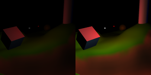
There are a few problems with our current lighting setup. It looks (mostly) fine in daylight. The moving point lights have a small visual effect, but mostly they're not very visible. And this is what one would expect in broad daylight; flashlights do not make much impact in the day.
But at night, everything is exceedingly dark. The point lights, the only active source of illumination, are all too dim to be very visible. The terrain almost completely blends into the black background.
There is an alternative set of light parameters that corrects this problem. Press Shift+L; that switches to a night-time optimized version (press L to switch back to day-optimized lighting). Here, the point lights provide reasonable lighting at night. The ground is still dark when facing away from the lights, but we can reasonably see things.
The problem is that, in daylight, the night-optimized point lights are too powerful. They are very visible and have very strong effects on the scene. Also, they cause some light problems when one of the point lights is in the right position. At around 12:50, find the floating white light near the cube:
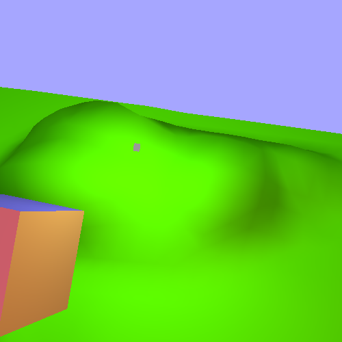
Notice the patch of iridescent green. This is light clipping or light clamping, and it is usually a very undesirable outcome. It happens when the computed light intensity falls outside of the [0, 1] range, usually in the positive direction (like in this case). The object cannot be shown to be brighter, so it becomes a solid color that loses all detail.
The obvious solution to our lighting problem is to simply change the point light intensity based on the time of day. However, this is not realistic; flashlights do not actually get brighter at night. So if we have to do something that antithetical to reality, then there's probably some aspect of reality that we are not properly modelling.