So, in order to deal with interpolation artifacts, we need to interpolate the actual light direction and normal, instead of just the results of the lighting equation. This is called per-fragment lighting or just fragment lighting.
This is pretty simple, conceptually. We simply need to do the lighting computations in the fragment shader. So the fragment shader needs the position of the fragment, the light's position (or the direction to the light from that position), and the surface normal of the fragment at that position. And all of these values need to be in the same coordinate space.
There is a problem that needs to be dealt with first. Normals do not interpolate well. Or rather, wildly different normals do not interpolate well. And light directions can be very different if the light source is close to the triangle relative to that triangle's size.
Consider the large plane we have. The direction toward the light will be very different at each vertex, so long as our light remains in relatively close proximity to the plane.
Part of the problem is with interpolating values along the diagonal of our triangle. Interpolation within a triangle works like this. For any position within the area of the triangle, that position can be expressed as a weighted sum of the positions of the three vertices.

The α, β, and γ values are not the distances from their respective points to the point of interest. In the above case, the point P is in the exact center of the triangle. Thus, the three values are each ⅓.
If the point of interest is along an edge of the triangle, then the contribution of the vertex not sharing that edge is zero.

Here, point P is exactly halfway between points C and B. Therefore, β, and γ are both 0.5, but α is 0.0. If point P is anywhere along the edge of a triangle, it gets none of its final interpolated value from the third vertex. So along a triangle's edge, it acts like the kind of linear interpolation we have seen before.
This is how OpenGL interpolates the vertex shader outputs. It takes the α, β, and γ coordinates for the fragment's position and combines them with the vertex output value for the three vertices in the same way it does for the fragment's position. There is slightly more to it than that, but we will discuss that later.
The ground plane in our example is made of two large triangles. They look like this:

What happens if we put the color black on the top-right and bottom-left points, and put the color green on the top-left and bottom-right points? If you interpolate these across the surface, you would get this:

The color is pure green along the diagonal. That is because along a triangle's edge, the value interpolated will only be the color of the two vertices along that edge. The value is interpolated based only on each triangle individually, not on extra data from another neighboring triangle.
In our case, this means that for points along the main diagonal, the light direction will only be composed of the direction values from the two vertices on that diagonal. This is not good. This would not be much of a problem if the light direction did not change much along the surface, but with large triangles (relative to how close the light is to them), that is simply not the case.
Since we cannot interpolate the light direction very well, we need to interpolate something else. Something that does exhibit the characteristics we need when interpolated.
Positions interpolate quite well. Interpolating the top-left position and bottom-right positions gets an accurate position value along the diagonal. So instead of interpolating the light direction, we interpolate the components of the light direction. Namely, the two positions. The light position is a constant, so we only need to interpolate the vertex position.
Now, we could do this in any space. But for illustrative purposes, we will be doing this in model space. That is, both the light position and vertex position will be in model space.
One of the advantages of doing things in model space is that it gets rid of that pesky matrix inverse/transpose we had to do to transform normals correctly. Indeed, normals are not transformed at all. One of the disadvantages is that it requires computing an inverse matrix for our light position, so that we can go from world space to model space.
The Fragment Point Lighting tutorial shows off how fragment lighting works.
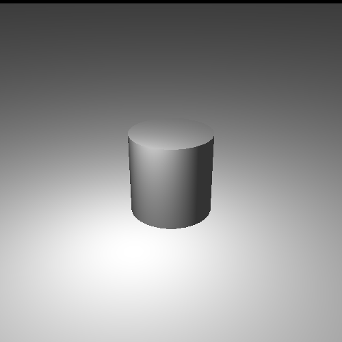
Much better.
This tutorial is controlled as before, with a few exceptions. Pressing the t key will toggle a scale factor onto to be applied to the cylinder, and pressing the h key will toggle between per-fragment lighting and per-vertex lighting.
The rendering code has changed somewhat, considering the use of model space for lighting instead of camera space. The start of the rendering looks as follows:
Example 10.3. Initial Per-Fragment Rendering
glutil::MatrixStack modelMatrix;
modelMatrix.SetMatrix(g_viewPole.CalcMatrix());

const glm::vec4 &worldLightPos = CalcLightPosition();

glm::vec4 lightPosCameraSpace = modelMatrix.Top() * worldLightPos;
The new code is the last line, where we transform the world-space light into camera space. This is done to make the math much easier. Since our matrix stack is building up the transform from model to camera space, the inverse of this matrix would be a transform from camera space to model space. So we need to put our light position into camera space before we transform it by the inverse.
After doing that, it uses a variable to switch between per-vertex and per-fragment lighting. This just selects which shaders to use; both sets of shaders take the same uniform values, even though they use them in different program stages.
The ground plane is rendered with this code:
Example 10.4. Ground Plane Per-Fragment Rendering
glutil::PushStack push(modelMatrix);

glUseProgram(pWhiteProgram->theProgram);
glUniformMatrix4fv(pWhiteProgram->modelToCameraMatrixUnif, 1, GL_FALSE,
glm::value_ptr(modelMatrix.Top()));

glm::mat4 invTransform = glm::inverse(modelMatrix.Top());
glm::vec4 lightPosModelSpace = invTransform * lightPosCameraSpace;
glUniform3fv(pWhiteProgram->modelSpaceLightPosUnif, 1, glm::value_ptr(lightPosModelSpace));

g_pPlaneMesh->Render();
glUseProgram(0);
We compute the inverse matrix using glm::inverse and store it.
Then we use that to compute the model space light position and pass that to the shader.
Then the plane is rendered.
The cylinder is rendered using similar code. It simply does a few transformations to the model matrix before computing the inverse and rendering.
The shaders are where the real action is. As with previous lighting tutorials, there are two sets of shaders: one that take a per-vertex color, and one that uses a constant white color. The vertex shaders that do per-vertex lighting computations should be familiar:
Example 10.5. Model Space Per-Vertex Lighting Vertex Shader
#version 330

layout(location = 0) in vec3 position;
layout(location = 1) in vec4 inDiffuseColor;
layout(location = 2) in vec3 normal;

out vec4 interpColor;

uniform vec3 modelSpaceLightPos;
uniform vec4 lightIntensity;
uniform vec4 ambientIntensity;

uniform mat4 modelToCameraMatrix;
uniform mat3 normalModelToCameraMatrix;

uniform Projection
{
    mat4 cameraToClipMatrix;
};

void main()
{
    gl_Position = cameraToClipMatrix * (modelToCameraMatrix * vec4(position, 1.0));

    vec3 dirToLight = normalize(modelSpaceLightPos - position);

    float cosAngIncidence = dot( normal, dirToLight);
    cosAngIncidence = clamp(cosAngIncidence, 0, 1);

    interpColor = (lightIntensity * cosAngIncidence * inDiffuseColor) +
        (ambientIntensity * inDiffuseColor);
}
The main differences between this version and the previous version are simply what one
would expect from the change from camera-space lighting to model space lighting. The
per-vertex inputs are used directly, rather than being transformed into camera space.
There is a second version that omits the inDiffuseColor input.
With per-vertex lighting, we have two vertex shaders:
ModelPosVertexLighting_PCN.vert and
ModelPosVertexLighting_PN.vert. With per-fragment lighting, we
also have two shaders: FragmentLighting_PCN.vert and
FragmentLighting_PN.vert. They are disappointingly
simple:
Example 10.6. Model Space Per-Fragment Lighting Vertex Shader
#version 330

layout(location = 0) in vec3 position;
layout(location = 1) in vec4 inDiffuseColor;
layout(location = 2) in vec3 normal;

out vec4 diffuseColor;
out vec3 vertexNormal;
out vec3 modelSpacePosition;

uniform mat4 modelToCameraMatrix;

uniform Projection
{
    mat4 cameraToClipMatrix;
};

void main()
{
    gl_Position = cameraToClipMatrix * (modelToCameraMatrix * vec4(position, 1.0));

    modelSpacePosition = position;
    vertexNormal = normal;
    diffuseColor = inDiffuseColor;
}
Since our lighting is done in the fragment shader, there is not much to do except pass variables through and set the output clip-space position. The version that takes no diffuse color just passes a vec4 containing just 1.0.
The fragment shader is much more interesting:
Example 10.7. Per-Fragment Lighting Fragment Shader
#version 330

in vec4 diffuseColor;
in vec3 vertexNormal;
in vec3 modelSpacePosition;

out vec4 outputColor;

uniform vec3 modelSpaceLightPos;

uniform vec4 lightIntensity;
uniform vec4 ambientIntensity;

void main()
{
    vec3 lightDir = normalize(modelSpaceLightPos - modelSpacePosition);

    float cosAngIncidence = dot(normalize(vertexNormal), lightDir);
    cosAngIncidence = clamp(cosAngIncidence, 0, 1);

    outputColor = (diffuseColor * lightIntensity * cosAngIncidence) +
        (diffuseColor * ambientIntensity);
}
The math is essentially identical between the per-vertex and per-fragment case. The
main difference is the normalization of vertexNormal. This is
necessary because interpolating between two unit vectors does not mean you will get a
unit vector after interpolation. Indeed, interpolating the 3 components guarantees that
you will not get a unit vector.
While this may look perfect, there is still one problem. Use the Shift+J key to move the light really close to the cylinder, but without putting the light inside the cylinder. You should see something like this:
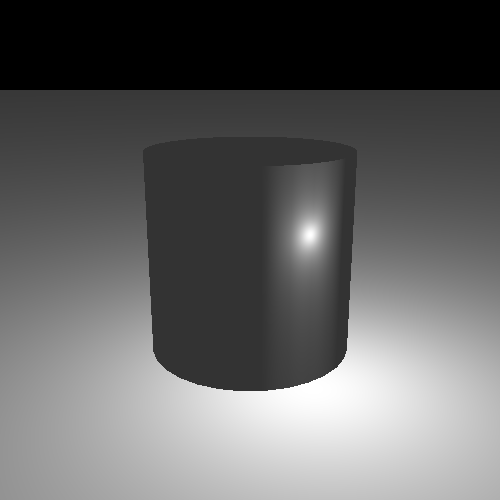
Notice the vertical bands on the cylinder. This are reminiscent of the same interpolation problem we had before. Was not doing lighting at the fragment level supposed to fix this?
It is similar to the original problem, but technically different. Per-vertex lighting caused lines because of color interpolation artifacts. This is caused by an optical illusion created by adjacent linear gradients.
The normal is being interpolated linearly across the surface. This also means that the lighting is changing somewhat linearly across the surface. While the lighting isn't a linear change, it can be approximated as one over a small area of the surface.
The edge between two triangles changes how the light interacts. On one side, the nearly-linear gradient has one slope, and on the other side, it has a different one. That is, the rate at which the gradients change abruptly changes.
Here is a simple demonstration of this:

These are two adjacent linear gradients, from the bottom left corner to the top right. The color value increases in intensity as it goes from the bottom left to the top right. They meet along the diagonal in the middle. Both gradients have the same color value in the middle, yet it appears that there is a line down the center that is brighter than the colors on both sides. But it is not; the color on the right side of the diagonal is actually brighter than the diagonal itself.
That is the optical illusion. Here is a diagram that shows the color intensity as it moves across the above gradient:

The color curve is continuous; there are no breaks or sudden jumps. But it is not a smooth curve; there is a sharp edge.
It turns out that human vision really wants to find sharp edges in smooth gradients. Anytime we see a sharp edge, our brains try to turn that into some kind of shape. And if there is a shape to the gradient intersection, such as a line, we tend to see that intersection “pop” out at us.
The solution to this problem is not yet available to us. One of the reasons we can see this so clearly is that the surface has a very regular diffuse reflectance (ie: color). If the surface color was irregular, if it changed at most every fragment, then the effect would be virtually impossible to notice.
But the real source of the problem is that the normal is being linearly interpolated. While this is certainly much better than interpolating the per-vertex lighting output, it does not produce a normal that matches with the normal of a perfect cylinder. The correct solution, which we will get to eventually, is to provide a way to encode the normal for a surface at many points, rather than simply interpolating vertex normals.