There is another issue with our current example. Use the i key to raise the light up really high. Notice how bright all of the upwardly-facing surfaces get:
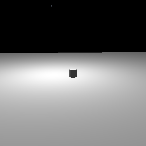
You probably have no experience with this in real life. Holding a light farther from the surface in reality does not make the light brighter. So obviously something is happening in reality that our simple lighting model is not accounting for.
In reality, lights emit a certain quantity of light per unit time. For a point-like light such as a light bulb, it emits this light radially, in all directions. The farther from the light source one gets, the more area that this must ultimately cover.
Light is essentially a wave. The farther away from the source of the wave, the less intense the wave is. For light, this is called light attenuation.
Our model does not include light attenuation, so let's fix that.
Attenuation is a well-understood physical phenomenon. In the absence of other factors (atmospheric light scattering, etc), the light intensity varies with the inverse of the square of the distance. An object 2 units away from the light feels the light with one-fourth the intensity. So our equation for light attenuation is as follows:
There is a constant in the equation, which is used for unit correction. Of course, we can (and will) use it as a fudge factor to make things look right.
The constant can take on a physical meaning. The constant can mean the distance at which half of the light intensity is lost. To compute such a constant, for a half-light distance of rλ, use this equation:
This equation computes physically realistic light attenuation for point-lights. But it often does not look very good. The equation tends to create a sharper intensity falloff than one would expect.
There is a reason for this, but it is not one we are ready to get into quite yet. What is often done is to simply use the inverse rather than the inverse-square of the distance:
It looks brighter at greater distances than the physically correct model. This is fine for simple examples, but as we get more advanced, it will not be acceptable. This solution is really just a stop-gap; the real solution is one that we will discuss in a few tutorials.
However, there is a problem. We previously did per-fragment lighting in model space. And while this is a perfectly useful space to do lighting in, model space is not world space.
We want to specify the attenuation constant factor in terms of world space distances. But we are not dealing in world space; we are in model space. And model space distances are, naturally, in model space, which may well be scaled relative to world space. Here, any kind of scale in the model-to-world transform is a problem, not just non-uniform scales. Although if there was a uniform scale, we could apply theoretically apply the scale to the attenuation constant.
So now we cannot use model space. Fortunately, camera space is a space that has the same scale as world space, just with a rotation/translation applied to it. So we can do our lighting in that space.
Doing it in camera space requires computing a camera space position and passing it to the fragment shader to be interpolated. And while we could do this, that's not clever enough. Is not there some way to get around that?
Yes, there is. Recall gl_FragCoord, an intrinsic value given to
every fragment shader. It represents the location of the fragment in window space.
So instead of transforming from model space to camera space, we will transform from
window space to camera space.
Note
The use of this reverse-transformation technique here should not be taken as a suggestion to use it in all, or even most cases like this. In all likelihood, it will be much slower than just passing the camera space position to the fragment shader. It is here primarily for demonstration purposes, and because it will be useful in the future.
The sequence of transformations that take a position from camera space to window space is as follows:
Table 10.1. Transform Legend
|
Field Name |
Meaning |
|---|---|
|
M | The camera-to-clip transformation matrix. |
|
Pcamera | The camera-space vertex position. |
|
C |
The clip-space vertex position. |
|
N |
The normalized device coordinate position. |
|
Vxy |
The X and Y values passed to
|
|
Vwh |
The width and height passed to
|
|
Dnf |
The depth near and far values passed to
|
Therefore, given gl_FragCoord, we will need to perform the
reverse of these:
In order for our fragment shader to perform this transformation, it must be given the following values:
-
The inverse projection matrix.
-
The viewport width/height.
-
The depth range.
The Fragment Attenuation tutorial performs per-fragment attenuation, both with linear and quadratic attenuation.
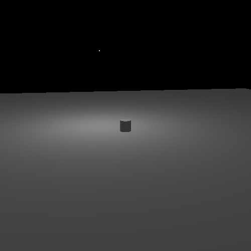
This tutorial controls as before, with the following exceptions. The O and U keys increase and decrease the attenuation constant. However, remember that decreasing the constant makes the attenuation less, which makes the light appear brighter at a particular distance. Using the shift key in combination with them will increase/decrease the attenuation by smaller increments. The H key swaps between the linear and quadratic interpolation functions.
The drawing code is mostly the same as we saw in the per-vertex point light tutorial, since both this and that one perform lighting in camera space. The vertex shader is also nothing new; passes the vertex normal and color to the fragment shader. The vertex normal is multiplied by the normal matrix, which allows us to use non-uniform scaling.
The more interesting part is the fragment shader. The definitions are not much changed from the last one, but there have been some additions:
Example 10.8. Light Attenuation Fragment Shader Definitions
uniform float lightAttenuation;
uniform bool bUseRSquare;

uniform UnProjection
{
    mat4 clipToCameraMatrix;
    ivec2 windowSize;
};
The lightAttenuation uniform is just a float, but
bUseRSquare uses a new type: boolean.
GLSL has the bool type just like C++ does. The
true and false values work just like C++'s
equivalents. Where they differ is that GLSL also has vectors of bools, called
bvec#, where the # can be 2, 3, or 4. We do not use that here, but
it is important to note.
OpenGL's API, however, is still a C API. And C (at least, pre-C99) has no bool type. Uploading a boolean value to a shader looks like this:
glUniform1i(g_FragWhiteDiffuseColor.bUseRSquareUnif, g_bUseRSquare ? 1 : 0);
The integer form of uniform uploading is used, but the floating-point form could be allowed as well. The number 0 represents false, and any other number is true.
The UnProjection uniform block contains data that only
changes when the window changes. This uniform block is updated along with the vertex
shader's Projection block. This data is used to perform the
previously-discussed reverse-transformation operation, so that we can turn
gl_FragCoord into a camera-space position.
Notice that the windowSize uses a new type: ivec2.
This is a 2-dimensional vector of integers.
For the first time, we have a shader complex enough that splitting it into different functions makes sense. So we do that. The first function is one that computes the camera-space position:
Example 10.9. Window to Camera Space Function
vec3 CalcCameraSpacePosition()
{
    vec4 ndcPos;
    ndcPos.xy = ((gl_FragCoord.xy / windowSize.xy) * 2.0) - 1.0;
    ndcPos.z = (2.0 * gl_FragCoord.z - gl_DepthRange.near - gl_DepthRange.far) /
        (gl_DepthRange.far - gl_DepthRange.near);
    ndcPos.w = 1.0;

    vec4 clipPos = ndcPos / gl_FragCoord.w;

    return vec3(clipToCameraMatrix * clipPos);
}
Not unsurprisingly, GLSL functions are defined much like C and C++ functions.
The first three lines compute the position in normalized device coordinates. Notice that the computation of the X and Y coordinates is simplified from the original function. This is because our viewport always sets the lower-left position of the viewport to (0, 0). This is what you get when you plug zeros into that equation.
The gl_DepthRange variable is a special uniform defined by GLSL
for fragment shaders. As the name suggests, it properly mirrors the values passed to
glDepthRange; this way, we do not have to put it in our
uniform block.
After the transformation to NDC space, we compute the clip-space position as previously shown. Then the result is multiplied through the clip-to-camera matrix, and that vector is returned to the caller.
This is a simple function that uses only uniforms to compute a value. It takes no arguments. The second function is not quite as simple.
Example 10.10. Light Intensity Application Function
vec4 ApplyLightIntensity(in vec3 cameraSpacePosition, out vec3 lightDirection)
{
    vec3 lightDifference =  cameraSpaceLightPos - cameraSpacePosition;
    float lightDistanceSqr = dot(lightDifference, lightDifference);
    lightDirection = lightDifference * inversesqrt(lightDistanceSqr);

    float distFactor = bUseRSquare ? lightDistanceSqr : sqrt(lightDistanceSqr);

    return lightIntensity * (1 / ( 1.0 + lightAttenuation * distFactor));
}
The function header looks rather different from the standard C/C++ function definition syntax. Parameters to GLSL functions are designated as being inputs, outputs, or inputs and outputs.
Parameters designated with in are input parameters. Functions
can change these values, but they will have no effect on the variable or expression
used in the function call. This is much like the default in C/C++, where parameter
changes are local. Naturally, this is the default with GLSL parameters if you do not
specify a qualifier.
Parameters designated with out can be written to, and its value
will be returned to the calling function. These are similar to non-const reference
parameter types in C++. And just as with reference parameters, the caller of a
function must call it with a real variable (called an “l-value”). And
this variable must be a variable that can be changed, so you
cannot pass a uniform or shader stage input value as this parameter.
However, the initial value of parameters declared as outputs is
not initialized from the calling function. This means that
the initial value is uninitialized and therefore undefined (ie: it could be
anything). Because of this, you can pass shader stage outputs as
out parameters. Recall that shader stage output variables can
be written to, but never read from.
Parameters designated as inout will have its value initialized
by the caller and have the final value returned to the caller. These are exactly
like non-const reference parameters in C++. The main difference is that the value is
initialized with the one that the user passed in, which forbids the passing of
shader stage outputs as inout parameters.
This particular function is semi-complex, as an optimization. Previously, our functions simply normalized the difference between the vertex position and the light position. In computing the attenuation, we need the distance between the two. And the process of normalization computes the distance. So instead of calling the GLSL function to normalize the direction, we do it ourselves, so that the distance is not computed twice (once in the GLSL function and once for us).
The second line performs a dot product with the same vector. Remember that the dot product between two vectors is the cosine of the angle between them, multiplied by each of the lengths of the vectors. Well, the angle between a vector and itself is zero, and the cosine of zero is always one. So what you get is just the length of the two vectors times one another. And since the vectors are the same, the lengths are the same. Thus, the dot product of a vector with itself is the square of its length.
To normalize a vector, we must divide the vector by it's length. And the length of
lightDifference is the square root of
lightDistanceSqr. The inversesqrt
computes 1 / the square root of the given value, so all we need to do is multiply
this with the lightDifference to get the light direction as a
normalized vector. This value is written to our output variable.
The next line computes our lighting term. Notice the use of the ?: operator. This works just like in C/C++. If we are using the square of the distance, that's what we store. Otherwise we get the square-root and store that.
Note
The assumption in using ?: here is that only one or the other of the two
expressions will be evaluated. That's why the expensive call to
sqrt is done here. However, this may not be the case.
It is entirely possible (and quite likely) that the shader will always evaluate
both expressions and simply store one value or the
other as needed. So do not rely on such conditional logic to save
performance.
After that, things proceed as expected.
Making these separate functions makes the main function look almost identical to prior versions:
Example 10.11. Main Light Attenuation
void main()
{
    vec3 cameraSpacePosition = CalcCameraSpacePosition();

    vec3 lightDir = vec3(0.0);
    vec4 attenIntensity = ApplyLightIntensity(cameraSpacePosition, lightDir);

    float cosAngIncidence = dot(normalize(vertexNormal), lightDir);
    cosAngIncidence = clamp(cosAngIncidence, 0, 1);

    outputColor = (diffuseColor * attenIntensity * cosAngIncidence) +
        (diffuseColor * ambientIntensity);
}
Function calls appear very similar to C/C++, with the exceptions about parameters noted before. The camera-space position is determined. Then the light intensity, modified by attenuation, is computed. From there, things proceed as before.