Linear mipmap filtering is good; it eliminates most of the fluttering and oddities in the distance. The problem is that it replaces a lot of that fluttering with... grey. Mipmap-based filtering works reasonably well, but it tends to over-compensate.
For example, take the diagonal chain of squares at the left or right of the screen. Expand the window horizontally if you need to.
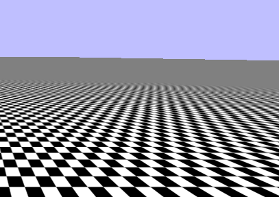
Pixels that are along this diagonal should be mostly black. As they get farther and farther away, the fragment area becomes more and more distorted length-wise, relative to the texel area:

With perfect filtering, we should get a value that is mostly black. But instead, we get a much lighter shade of grey. The reason has to do with the specifics of mipmapping and mipmap selection.
Mipmaps are pre-filtered versions of the main texture. The problem is that they are filtered in both directions equally. This is fine if the fragment area is square, but for oblong shapes, mipmap selection becomes more problematic. The particular algorithm used is very conservative. It selects the smallest mipmap level possible for the fragment area. So long, thin areas, in terms of the values fetched by the texture function, will be no different from a square area.

The large square represents the effective filtering box, while the diagonal area is the one that we are actually sampling from. Mipmap filtering can often combine texel values from outside of the sample area, and in this particularly degenerate case, it pulls in texel values from very far outside of the sample area.
This happens when the filter box is not a square. A square filter box is said to be isotropic: uniform in all directions. Therefore, a non-square filter box is anisotropic. Filtering that takes into account the anisotropic nature of a particular filter box is naturally called anisotropic filtering.
The OpenGL specification is usually very particular about most things. It explains the details of which mipmap is selected as well as how closeness is defined for linear interpolation between mipmaps. But for anisotropic filtering, the specification is very loose as to exactly how it works.
The general idea is this. The implementation will take some number of samples that approximates the shape of the filter box in the texture. It will select from mipmaps, but only when those mipmaps represent a closer filtered version of area being sampled. Here is an example:

Some of the samples that are entirely within the sample area can use smaller mipmaps to reduce the number of samples actually taken. The above image only needs four samples to approximate the sample area: the three small boxes, and the larger box in the center.
All of the sample values will be averaged together based on a weighting algorithm that best represents that sample's contribution to the filter box. Again, this is all very generally; the specific algorithms are implementation dependent.
Run the tutorial again. The 5 key turns activates a form of anisotropic filtering.
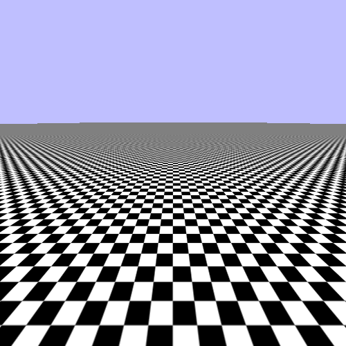
That's an improvement.
Anisotropic filtering requires taking multiple samples from the various mipmaps. The control on the quality of anisotropic filtering is in limiting the number of samples used. Raising the maximum number of samples taken will generally make the result look better, but it will also decrease performance.
This is done by setting the GL_TEXTURE_MAX_ANISOTROPY_EXT
sampler parameter:
glSamplerParameteri(g_samplers[4], GL_TEXTURE_MAG_FILTER, GL_LINEAR);
glSamplerParameteri(g_samplers[4], GL_TEXTURE_MIN_FILTER, GL_LINEAR_MIPMAP_LINEAR);
glSamplerParameterf(g_samplers[4], GL_TEXTURE_MAX_ANISOTROPY_EXT, 4.0f);
This represents the maximum number of samples that will be taken for any texture accesses through this sampler. Note that we still use linear mipmap filtering in combination with anisotropic filtering. While you could theoretically use anisotropic filtering without mipmaps, you will get much better performance if you use it in tandem with linear mipmap filtering.
The max anisotropy is a floating point value, in part because the specific nature of anisotropic filtering is left up to the hardware. But in general, you can treat it like an integer value.
There is a limit to the maximum anisotropy that we can provide. This limit is
implementation defined; it can be queried with glGetFloatv,
since the value is a float rather than an integer. To set the max anisotropy to the
maximum possible value, we do this.
GLfloat maxAniso = 0.0f;
glGetFloatv(GL_MAX_TEXTURE_MAX_ANISOTROPY_EXT, &maxAniso);

glSamplerParameteri(g_samplers[5], GL_TEXTURE_MAG_FILTER, GL_LINEAR);
glSamplerParameteri(g_samplers[5], GL_TEXTURE_MIN_FILTER, GL_LINEAR_MIPMAP_LINEAR);
glSamplerParameterf(g_samplers[5], GL_TEXTURE_MAX_ANISOTROPY_EXT, maxAniso);
To see the results of this, press the 6 key.

That looks pretty good now. There are still some issues out in the distance. Remember that your image may not look exactly like this one, since the details of anisotropic filtering are implementation specific.
You may be concerned that none of the filtering techniques produces perfect results, even the max anisotropic one. In the distance, the texture still becomes a featureless grey even along the diagonal. The reason is because rendering large checkerboard is perhaps one of the most difficult problems from a texture filtering perspective. This becomes even worse when it is viewed edge on, as we do here.
Indeed, the repeating checkerboard texture was chosen specifically because it highlights the issues in a very obvious way. A more traditional diffuse color texture typically looks much better with reasonable filtering applied. Also, there is one issue that we are currently missing that will be applied in the next tutorial.
You may have noticed the “EXT” suffix on
GL_TEXTURE_MAX_ANISOTROPY_EXT. This suffix means that this
enumerator comes from an OpenGL extension. First and
foremost, this means that this enumerator is not part of the OpenGL
Specification.
An OpenGL extension is a modification of OpenGL exposed by a particular implementation. Extensions have published documents that explain how they change the standard GL specification; this allows users to be able to use them correctly. Because different implementations of OpenGL will implement different sets of extensions, there is a mechanism for querying whether an extension is implemented. This allows user code to detect the availability of certain hardware features and use them or not as needed.
There are several kinds of extensions. There are proprietary extensions; these are created by a particular vendor and are rarely if ever implemented by another vendor. In some cases, they are based on intellectual property owned by that vendor and thus cannot be implemented without explicit permission. The enums and functions for these extensions end with a suffix based on the proprietor of the extension. An NVIDIA-only extension would end in “NV,” for example.
ARB extensions are a special class of extension that is blessed by the OpenGL ARB (who governs the OpenGL specification). These are typically created as a collaboration between multiple members of the ARB. Historically, they have represented functionality that implementations were highly recommended to implement.
EXT extensions are a class between the two. They are not proprietary extensions, and in many cases were created through collaboration among ARB members. Yet at the same time, they are not “blessed” by the ARB. Historically, EXT extensions have been used as test beds for functionality and APIs, to ensure that the API is reasonable before promoting the feature to OpenGL core or to an ARB extension.
The GL_TEXTURE_MAX_ANISOTROPY_EXT enumerator is part of the
EXT_texture_filter_anisotropic extension. Since it is an extension rather than core
functionality, it is usually necessary for the user to detect if the extension is
available and only use it if it was. If you look through the tutorial code, you will
find no code that does this test.
The reason for that is simply a lack of need. The extension itself dates back to the GeForce 256 (not the GeForce 250GT; the original GeForce), way back in 1999. Virtually all GPUs since then have implemented anisotropic filtering and exposed it through this extension. That is why the tutorial does not bother to check for the presence of this extension; if your hardware can run these tutorials, then it exposes the extension.
If it is so ubiquitous, why has the ARB not adopted the functionality into core OpenGL? Why must anisotropic filtering be an extension that is de facto guaranteed but not technically part of OpenGL? This is because OpenGL must be Open.
The “Open” in OpenGL refers to the availability of the specification, but also to the ability for anyone to implement it. As it turns out, anisotropic filtering has intellectual property issues associated with it. If it were adopted into the core, then core OpenGL would not be able to be implemented without licensing the technology from the holder of the IP. It is not a proprietary extension because none of the ARB members have the IP; it is held by a third party.
Therefore, you may assume that anisotropic filtering is available through OpenGL. But it is technically an extension.